Light control sheet and method of manufacturing the sheet

Inactive Publication Date: 2005-03-31
DAICEL CHEM IND LTD
View PDF9 Cites 25 Cited by
  • Summary
  • Abstract
  • Description
  • Claims
  • Application Information

AI Technical Summary

Benefits of technology

[0013] It is a further object of the invention to a light control sheet which is capable of reducing asymmetry in an angle dependence of brightness of a light emitted from a light guide plate in a back light unit comprising a tubular light source on one side thereof, and improving a front luminance of a display surface, as well as a process for producing the same.
[0014] It is a still further object of the invention to a process for easily producing a light control sheet at a low cost without using holography technology.
[0015] A further object of the invention is to provide a back light unit capable of improving a front luminance characteristic in a display surface of a liquid crystal display apparatus.
[0016] The inventors of the present invention made intensive studies to achieve the above objects and finally found that dispersing a platelike (or plate-like) particle having a given aspect ratio in a transparent resin and shee

Problems solved by technology

However, since a conventional light-scattering sheet is produced by mat finishing a surface of a transparent resin sheet, by dispersing a scattering fine particle into the inside of the transparent resin sheet, or by other means, the sheet does not have the foregoing light control function.
However, such a sheet is produced by photo-curing based on holography technology, resulting in generation of interference colors or significant increase of production cost.
However, due to irregularity of the shape and thickness of the scattering factor, directivity of the scattering light is deteriorated, or selectivity of the incident angle of light is decreased.
Further, t

Method used


Image

  • Light control sheet and method of manufacturing the sheet
  • Light control sheet and method of manufacturing the sheet
  • Light control sheet and method of manufacturing the sheet

Examples


example 1

[0119]

[0120] With 100 parts by weight of a cellulose acetate flake (manufactured by Daicel Chemical Industries, Ltd., acetylation degree of 53%), 50 parts by weight of diethyl phthalate and 1 part by weight of a stabilizer were blended to give an original flake of a transparent resin sheet, wherein the stabilizer was a mixture containing “PHOSPHITE PEP36” (manufactured by Asahi Denka Co., Ltd.), an epoxidized soybean oil “DAIMAC S-300K” (manufactured by Daicel Chemical Industries, Ltd.) and an antioxidant “ANTI-OX L” (manufactured by NOF Corporation) at a proportion of 4:4:2 (weight ratio). To this original flake was added 3 parts by weight of a transparent mica fine particle (“PDM10B” manufactured by Topy Industries, Ltd., mean diameter at surface direction: 12 μm, thickness: 0.2 μm), and the mixture was heated at 235° C., kneaded, and solidified in a cold water to cut into a pellet. The pellet was dried at 90° C. for 2 hours, then heated at 180° C., kneaded, and extruded into a sh...

example 2

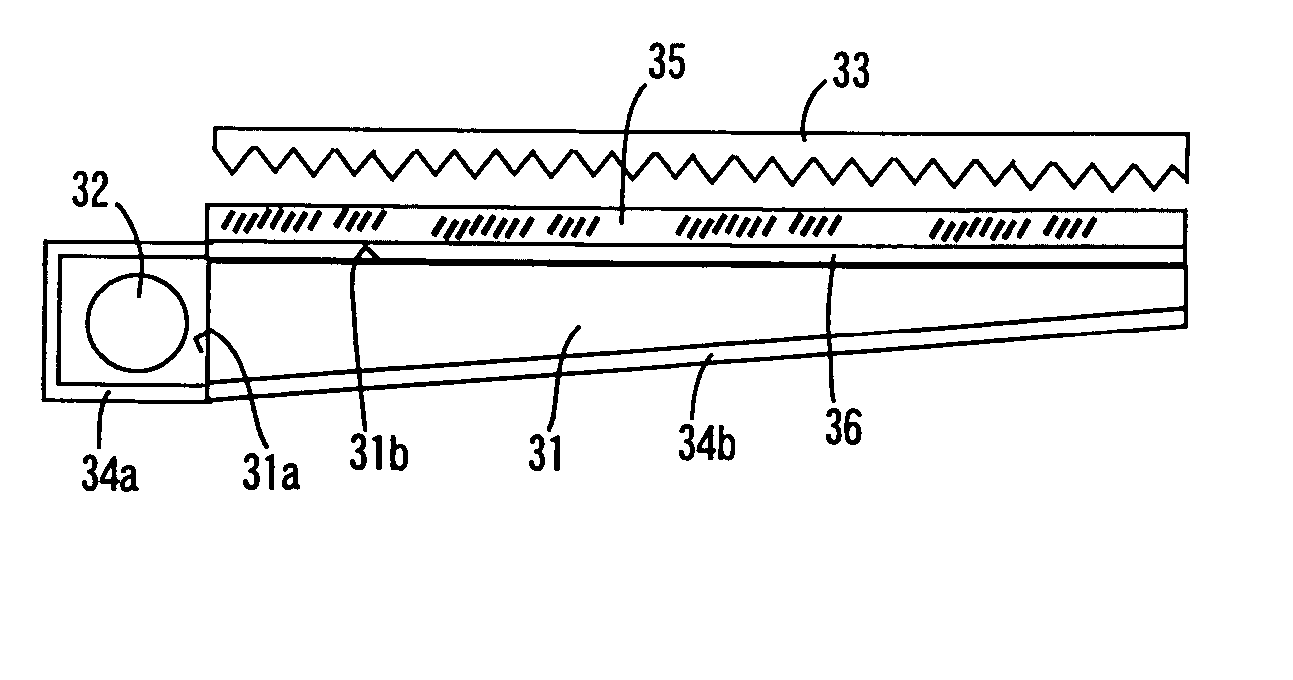
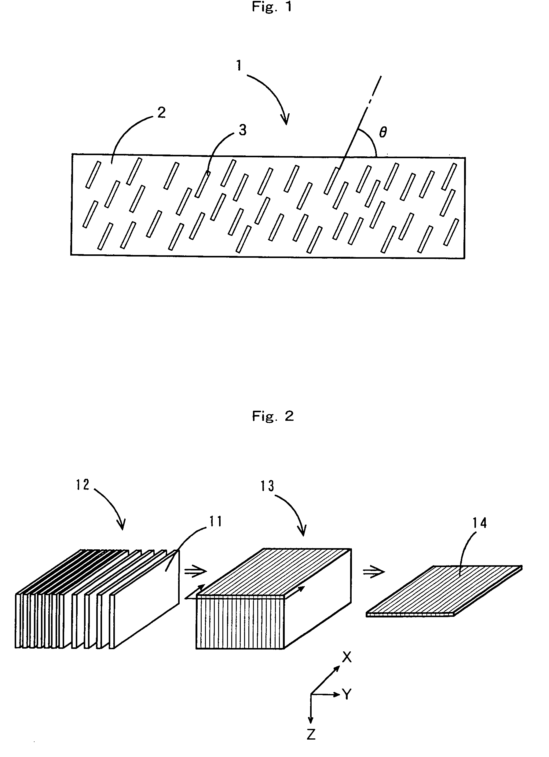
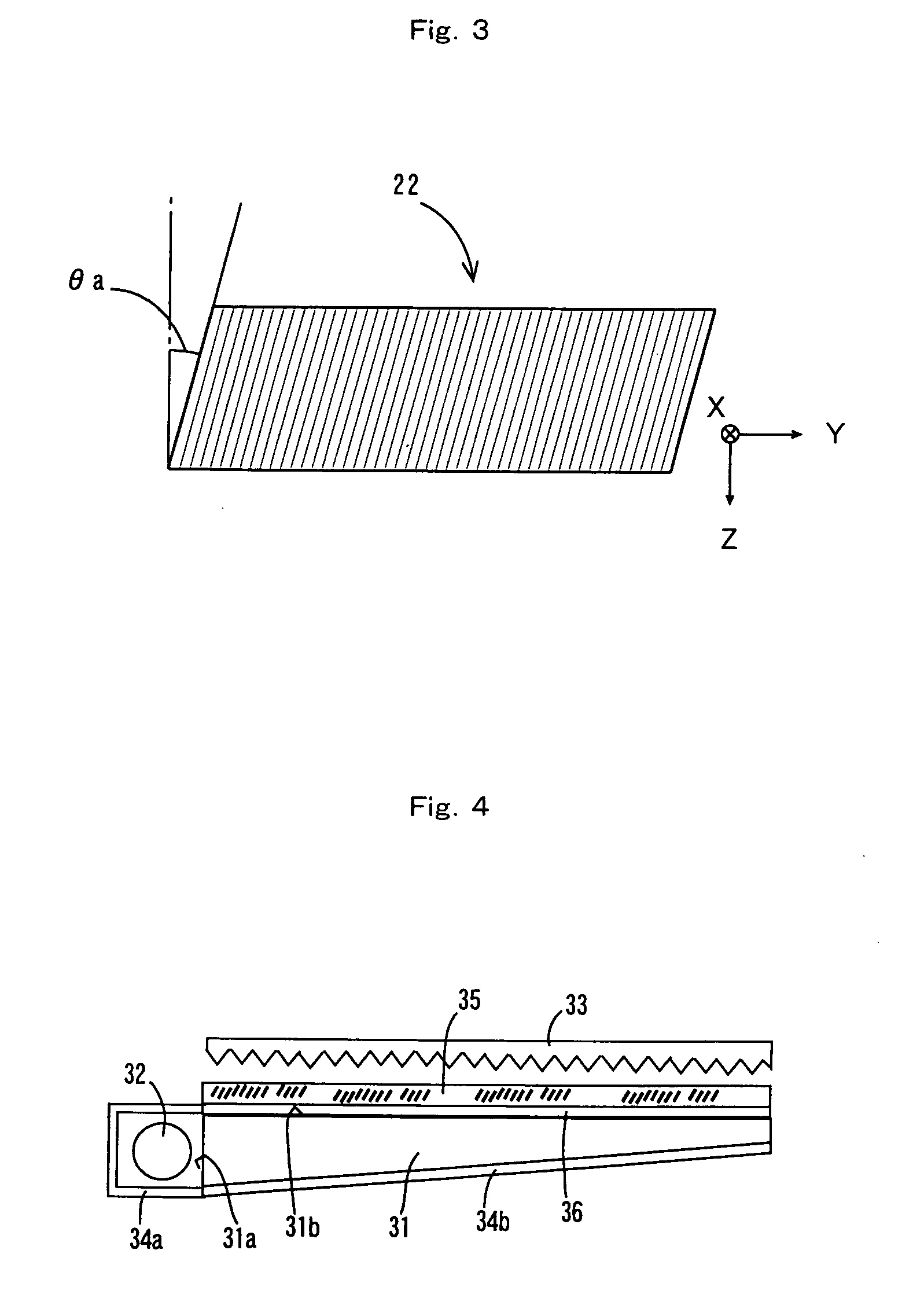
[0127] The primary sheet prepared in Example 1 was cut off by a length of 30 cm along the X-axial direction to make strip-like primary sheets. As shown in FIG. 3, 400 pieces of the strip-like primary sheets were laminated (or layered) so that the top of the primary sheets was tilted in a lateral direction at an angle θa of 10° to the perpendicular line. The multilayer mass was heated to 180° C. with pressing the both sides thereof to weld the primary sheets of the multilayer mass each other, and a block of which the both sides were inclined by an angle of 10° was produced. This block was sliced to a thickness of 0.6 mm along the X-axial direction (X-Y plane) so that the Z-axial direction was defined as the thickness direction to obtain a light control sheet.

[0128]FIG. 8 shows a cross sectional view along the Y-Z plane of this light control sheet (photomicrograph). As shown in this figure, the mica fine particle in the sheet was uniformly oriented so that the angle of the plate surf...

example 3

[0129] A light control sheet 0.8 mm thick was obtained in the same manner as in Example 2 except that the angle of inclination θa of the block lateral side was taken as 15°. The observation of the section along the Y-Z plane in this light control sheet revealed that the mica fine particle in the sheet was uniformly oriented so that the angle of the normal line of the plate surface to the normal line of the sheet surface was 75°.


PUM


Abstract

A light control sheet 1 having a platelike particle 3 (e.g., a mica) dispersedly oriented in a transparent resin 2 is obtained by laminating a plurality of transparent resin sheets in which the plate surface of the platelike particle is oriented along the sheet surface, welding these sheets to each other, and slicing the resulting matter in an intersecting direction relative to the laminating direction. The platelike particle comprises a transparent particle or a reflective particle. The direction of the plate surface of the fine particle is inclined to the sheet surface, and the angle θ of the plate surface of the platelike particle 3 to the plane of the sheet 1 is about 45 to 90°. Thus obtained light control sheet has a function in which an incident light in a specific angle range is selectively scattered, or a function in which an angle dependence of brightness can be improved even when a light source is locally disposed to a display surface or a light guide plate.

Description

TECHNICAL FIELD [0001] The present invention relates to a light control sheet not only improving in luminance or an angle dependence of brightness (or luminance) but also selectively scattering lights entered with various angles, and useful for decoration, in optical system of a display apparatus such as a liquid crystal display apparatus, as well as a process for producing the sheet. [0002] Moreover, the invention relates to a light control sheet that ensures improvement in an angle dependence of brightness (or luminance) in a back light unit for illuminating a display surface of a display apparatus (such as a liquid crystal display apparatus) from a back side thereof with a tubular light source (a back light unit having a one-sided light source lamp), as well as a process for producing the sheet. BACKGROUND ART [0003] Up to now, a light-diffusing sheet has been used in order to improve luminance or an angle dependence of brightness, luminance uniformity or others, in a liquid crys...

Claims


Application Information

Patent Timeline
IPC IPC(8): F21V8/00G02B5/02
CPCG02B5/0242G02B5/0257G02B6/0041G02B6/0033G02B5/0278G02F1/1335
Inventor TAKEMOTO, HIROYUKIOHNISHI, MASANARI
Owner DAICEL CHEM IND LTD
Why Eureka
Try Eureka