Magnetic recording medium and method for manufacturing the same

a technology of magnetic recording medium and manufacturing method, which is applied in special recording techniques, instruments, nanoinformatics, etc., can solve the problems of affecting the quality of magnetic recording medium, etc., to achieve excellent durability and high density recording

Active Publication Date: 2005-03-31
KK TOSHIBA
View PDF10 Cites 68 Cited by
  • Summary
  • Abstract
  • Description
  • Claims
  • Application Information

AI Technical Summary

Benefits of technology

[0016] In view of the above circumstances, an object of the present invention is to provide a magnetic recording medium which allows high density recording and has an excellent durability and a method for manufacturing the same.

Problems solved by technology

However, fineness of the recording bit makes a magnetization amount per bit small, which causes such a problem as disappearing of magnetized information or data due to magnetization reversal due to “thermal fluctuation”.
However, when high density of the magnetic recording medium further advances in the future, a limit will appear in robustness to the “thermal fluctuation” even in the perpendicular magnetic recording system.
On the other hand, when a track density is improved, a problem about interference with an adjacent track is developed.
In particular, reduction of writing blurring due to a recording head magnetic fringe effect is a important technical problem.
However, when record is written in each of the patterned media and the discrete track media, magnetic field is concentrated on a corner of a recording track (or a recording bit) so that electrostatic discharge occurs due to sparking.
Such a problem arises that a magnetic material deteriorates due to such a local electrostatic discharge, life of each of the patterned media and the discrete track media (hereinafter, called “patterned media, too) is shortened.
There is also a problem that the patterned media is inferior in lubricant application to the conventional continuous film.
Furthermore, as the cause of life reduction of the patterned media, there is an abnormal protrusion on the medium surface.
In addition to such a risk that the abnormal protrusion and the recording / reproducing head collides with each other to cause failure, the recording / reproducing head and the magnetic recording medium degrades due to influence of heat generated by the collision.
In the patterned media, a hard mask (usually, metal such as Ti or Ta) is used for working a magnetic material, but it is difficult to remove the hard mask and a portion of the hard mask which can not be removed causes the abnormal protrusion.

Method used


Image

  • Magnetic recording medium and method for manufacturing the same
  • Magnetic recording medium and method for manufacturing the same
  • Magnetic recording medium and method for manufacturing the same

Examples


example 1

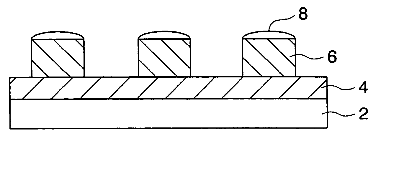
[0109] CoZrNb with a film thickness of 200 nm constituting a soft magnetic layer was formed on a glass substrate. Then, CoCrPt alloy with a thickness of 15 nm was formed as a ferromagnetic layer, and carbon with a thickness of 20 nm was formed thereon by CVD process. Thereafter, after a resist with a film thickness of 50 nm was formed, undulation was formed by a nano-imprint process using a Ni stamper with a whole surface on which a land / group pattern with a pitch of 400 nm and a land portion of 200 nm was formed by Deep UV cutting process. Subsequently, imprint residue was removed by weak RIE of 100 w using oxygen gas, and the carbon film was etched using strong RIE of 200 W, so that a carbon hard mask was formed. Thereafter, a patterned media (discrete track media) was obtained by etching the CoCrPt alloy, which was the ferromagnetic layer, by a thickness of 15 nm by using Ar ion milling.

[0110] An etching process where an ion incident angle was gradually varied from a vertical di...

example 2

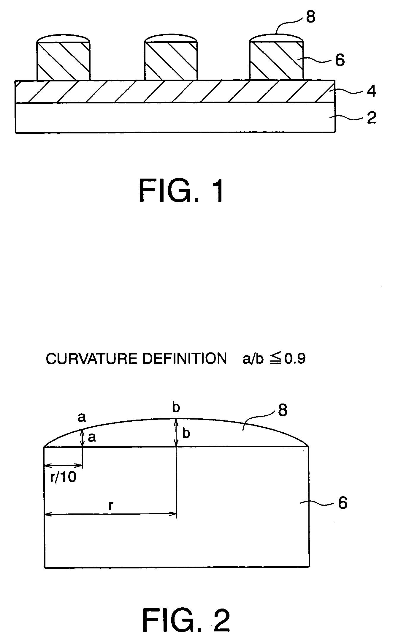
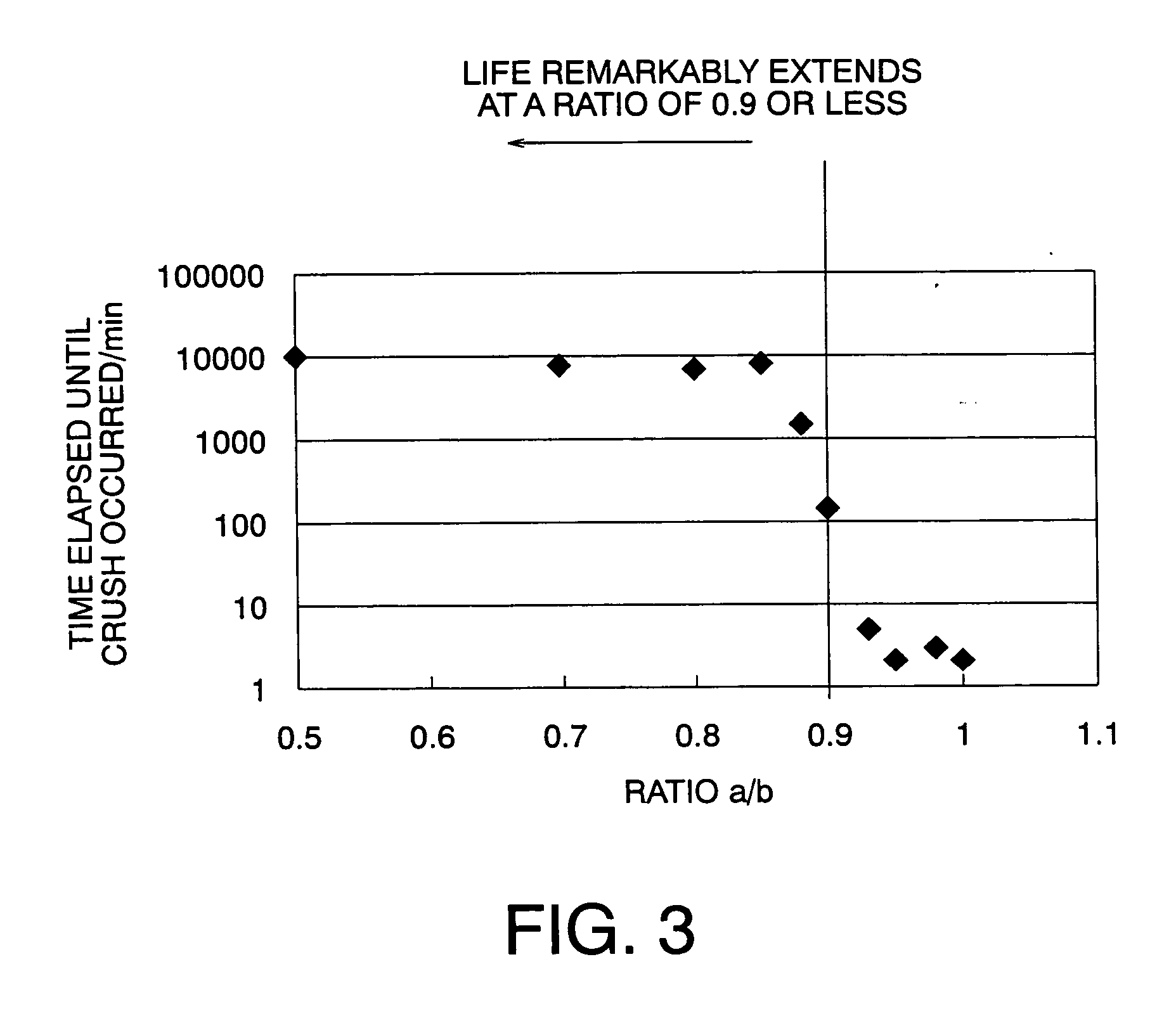
[0114] In Example 1, samples with such a structure that a film thickness “a” of an end portion of the carbon film decreased as compared with a film thickness b at a central portion thereof were manufactured while conditions were being changed. Regarding all the samples, a durability test was conducted using a floating type recording / reproducing head, and ratios a / b and times elapsing until a recording / reproducing waveform was not observed were plotted. As shown in FIG. 3, a clear threshold value was found. That is, regarding samples with a ratio a / b of 0.9 or less, durability over about several days to one week was confirmed, but it was found that the recording / reproducing head was broken regarding samples with a ratio a / b of 0.9 or more.

example 3

[0115] When the conventional patterned media manufactured in Comparative Example 1 was tested using a floating type head, the floating type head was attached with an AE (Acoustic Emission) sensor, and integral values were plotted regarding time, so that a graph g1 shown in FIG. 29 was obtained. That is, a noise output began to increase after about 15 minutes elapsed from a test start. This means such a fact that a free layer portion in lubricant is poor. It was found that replenishment could not be performed to decrease of lubricant caused by pin off due to a centrifugal force or a head contact.

[0116] On the other hand, samples manufactured in Example 1 were measured in the same manner and a graph g2 shown in FIG. 29 was obtained. A noise output of the AE sensor hardly changed, and it was found that sufficient replenishment to decrease of lubricant could be made.

[0117] As explained above, according to each embodiment of the present invention, a magnetic recording medium which allo...


PUM

PropertyMeasurementUnit
thicknessaaaaaaaaaa
thicknessaaaaaaaaaa
angleaaaaaaaaaa

Abstract

A magnetic recording medium which allows high density recording and has excellent durability can be obtained. A magnetic recording medium includes: a plurality of ferromagnetic material dots arranged on a soft magnetic layer formed on a non-magnetic substrate so as to be separated from one another; and carbon films which are formed on the respective ferromagnetic material dots, each carbon film having a smooth film face shape in a section passing through the center of each ferromagnetic material dot and a film thickness gradually decreasing from the center of the ferromagnetic material dot toward an outer edge thereof.

Description

CROSS-REFERENCE TO RELATED APPLICATION [0001] This application is base upon and claims the benefit of priority from prior Japanese Patent Application No. 2003-341304, filed on Sep. 30, 2003 in Japan, the entire contents of which are incorporated herein by reference. BACKGROUND OF THE INVENTION [0002] 1. Field of the Invention [0003] The present invention relates to a magnetic recording medium which allows high density magnetic recording and a method for manufacturing the same. [0004] 2. Related Art [0005] In recent years, multimedia for data such as image, video, sound progresses, which results in increase in information or data volume of retrieval data per one user. For this reason, mass volume of database and fast processing are required. On the other hand, according to improvement of surface recording density of a magnetic recording medium due to increase in recording volume of HDD (Hard Disk Drive), each recording bit size on the magnetic recording medium becomes extremely fine ...

Claims


Application Information

Patent Timeline
Patent Type & Authority Applications(United States)
IPC IPC(8): G11B5/72G11B5/00G11B5/65G11B5/667G11B5/74G11B5/855
CPCB82Y10/00G11B5/74G11B5/743Y10T428/265G11B2005/001Y10T428/256G11B5/855
Inventor KAMATA, YOSHIYUKIOHSAWA, YUICHIHIEDA, HIROYUKIKIKITSU, AKIRA
Owner KK TOSHIBA
Why Eureka
Try Eureka