
Temperature sensing circuit for use in semiconductor integrated circuit

Inactive Publication Date: 2005-04-07
SAMSUNG ELECTRONICS CO LTD
View PDF23 Cites 72 Cited by
  • Summary
  • Abstract
  • Description
  • Claims
  • Application Information

AI Technical Summary

Benefits of technology

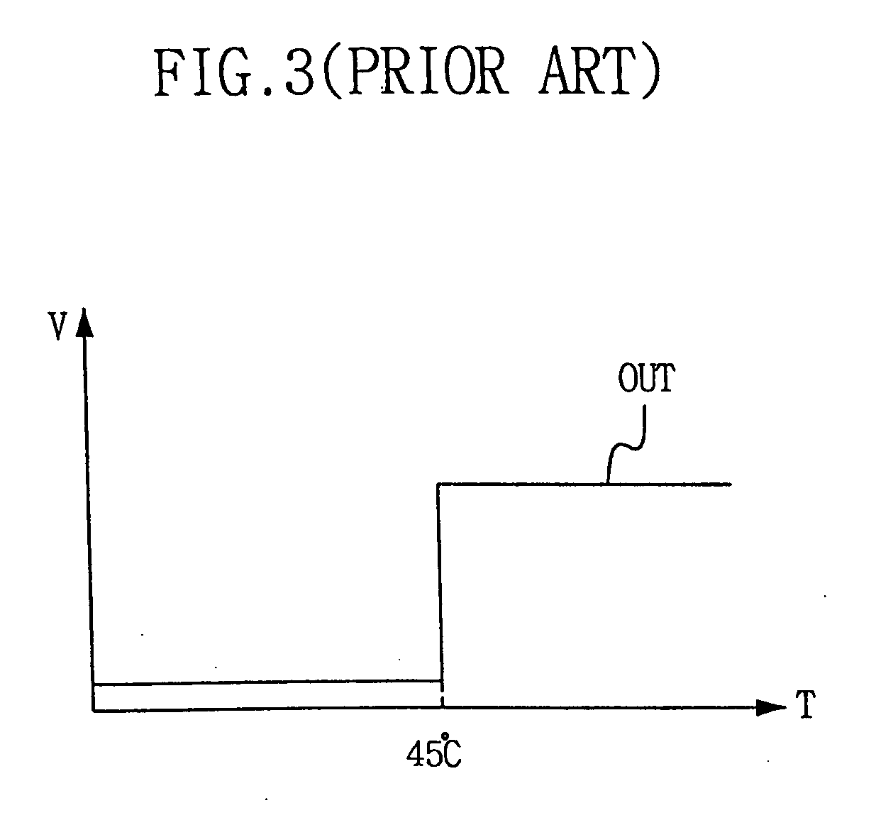
[0006] One technique to reduce the electrical power needed for the self-refresh is to change the refresh cycle in conformity with the temperature. The data preservation time in a DRAM becomes longer at reduced temperatures. Thus, the temperature range is divided into several regions, and the frequency of the refresh clock is lowered relatively at a low temperature region, to thus reduce the consumption of electrical power. Herewith, in order to obtain an internal temperature of a DRAM, a built-in temperature sensor having low electrical power consumption is required.
[0024] Some example embodiments of the present invention provide a built-in temperature sensing circuit capable of substantially reducing a self-refresh electrical power consumption of a semiconductor memory device in conformity with a temperature change.
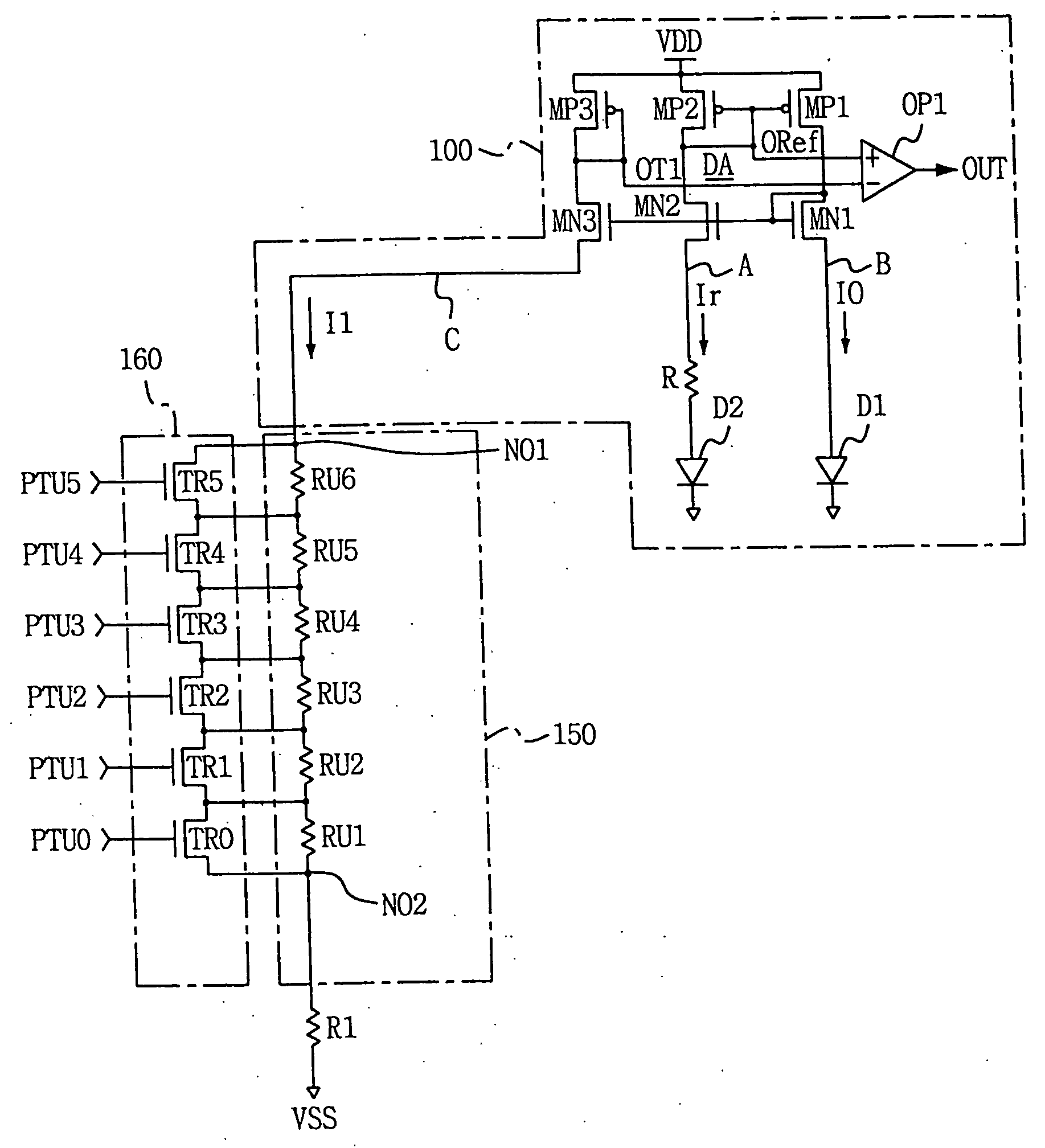
[0039] Accordingly, numerous trip points can be provided by a temperature change without extending the number of decrease resistance branches, that is, a required fine control can be performed in conformity with the temperature change.

Problems solved by technology

Meanwhile, however, reducing the electrical power in a battery operated system requiring a lower electrical power is very important and critical.
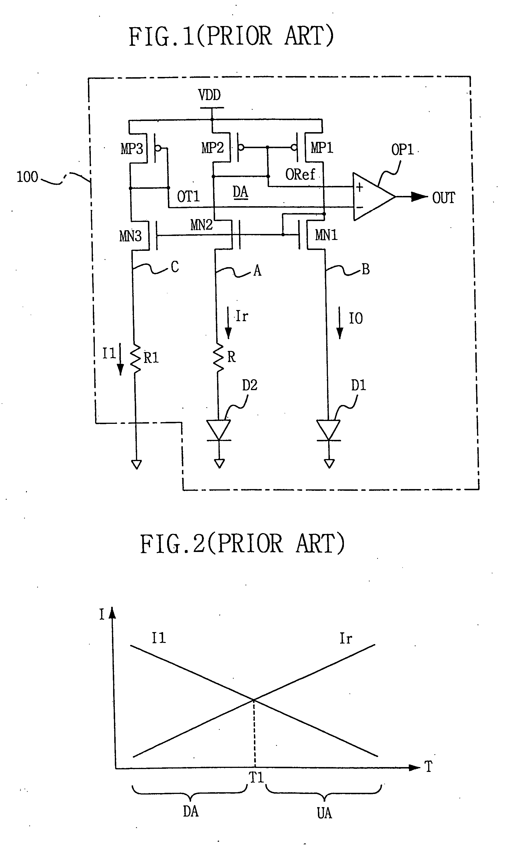
However, in a general control of the refresh cycle, the temperature sensor having two trip points is used, which is why there are problems such an increased time to perform a resistance trimming operation based on a process change, and an extension of the area occupied by the temperature sensor, in case the temperature sensor is provided with more than two branches.
That is, there was the difficulty to have numerous trip points in the conventional temperature sensor.
In employing the conventional temperature sensor in the semiconductor memory device, a refresh cycle of the semiconductor memory is difficult to be appropriately controlled by a temperature change without a rapid change of a refresh cycle control, thus reliability of a semiconductor device may be dropped.

Method used


Image

  • Temperature sensing circuit for use in semiconductor integrated circuit
  • Temperature sensing circuit for use in semiconductor integrated circuit
  • Temperature sensing circuit for use in semiconductor integrated circuit

Examples


Embodiment Construction

[0054] Hereinafter, example embodiments of the present invention will be described in detail with reference to FIGS. 4 to 14 in which like components having like functions have been provided with like reference symbols and numerals.

[0055] It will be understood by those skilled in the art that the present invention can be embodied by numerous different types and is not limited to the following described embodiments. The following various embodiments are examples in nature.

[0056]FIG. 4 shows a circuit diagram of a temperature sensor according to an exemplary embodiment. Referring to FIG. 4, there is shown a structure wherein a first resistance string part 150 and a short-circuit switching part 160 are connected to a decrease resistance branch C of a temperature sensor 100 such as that shown in FIG. 1.

[0057] The temperature sensor of FIG. 4 includes a differential amplifier DA of a current mirror type, a decrease resistance branch C, which is connected between a decrease resistance ...


PUM


Abstract

A temperature sensing circuit has numerous trip points in conformity with a temperature change without adding decrease resistance branches, so as to obtain a fine control based on the temperature change. Accordingly, when employed in a semiconductor memory device, the temperature sensing circuit substantially reduces the consumption of refresh electrical power in a stand-by state without decreasing the reliability of the semiconductor memory device.

Description

CROSS REFERENCES TO RELATED APPLICATIONS [0001] This application claims priority under 35 U.S.C. § 119 from Korean Patent Application 2003-69069, filed on Oct. 6, 2003, the contents of which are hereby incorporated by reference in their entirety for all purposes as if fully set forth herein.BACKGROUND AND SUMMARY [0002] 1. Technical Field [0003] The present invention relates to a temperature sensor. More particularly, the present invention relates to a temperature sensor circuit for use in a semiconductor integrated circuit. [0004] 2. Description of the Related Art [0005] Various semiconductor devices embodied with integrated circuit chips, such as CPUs, memories and gate arrays etc., are incorporated in various electrical products such as portable personal computers, Personal Digital Assistants (PDAs), servers or workstations. While these electrical products have a sleep mode for saving electrical power, most circuit components become a turn-off state. However, a Dynamic Random Acc...

Claims


Application Information

Patent Timeline
IPC IPC(8): G01K3/00G11C11/40G11C7/04
CPCG01K3/005G11C11/40
Inventor WON, MYUNG-GYOOKIM, JAE-HOONPARK, JONG-WOOK
Owner SAMSUNG ELECTRONICS CO LTD
Learn More