

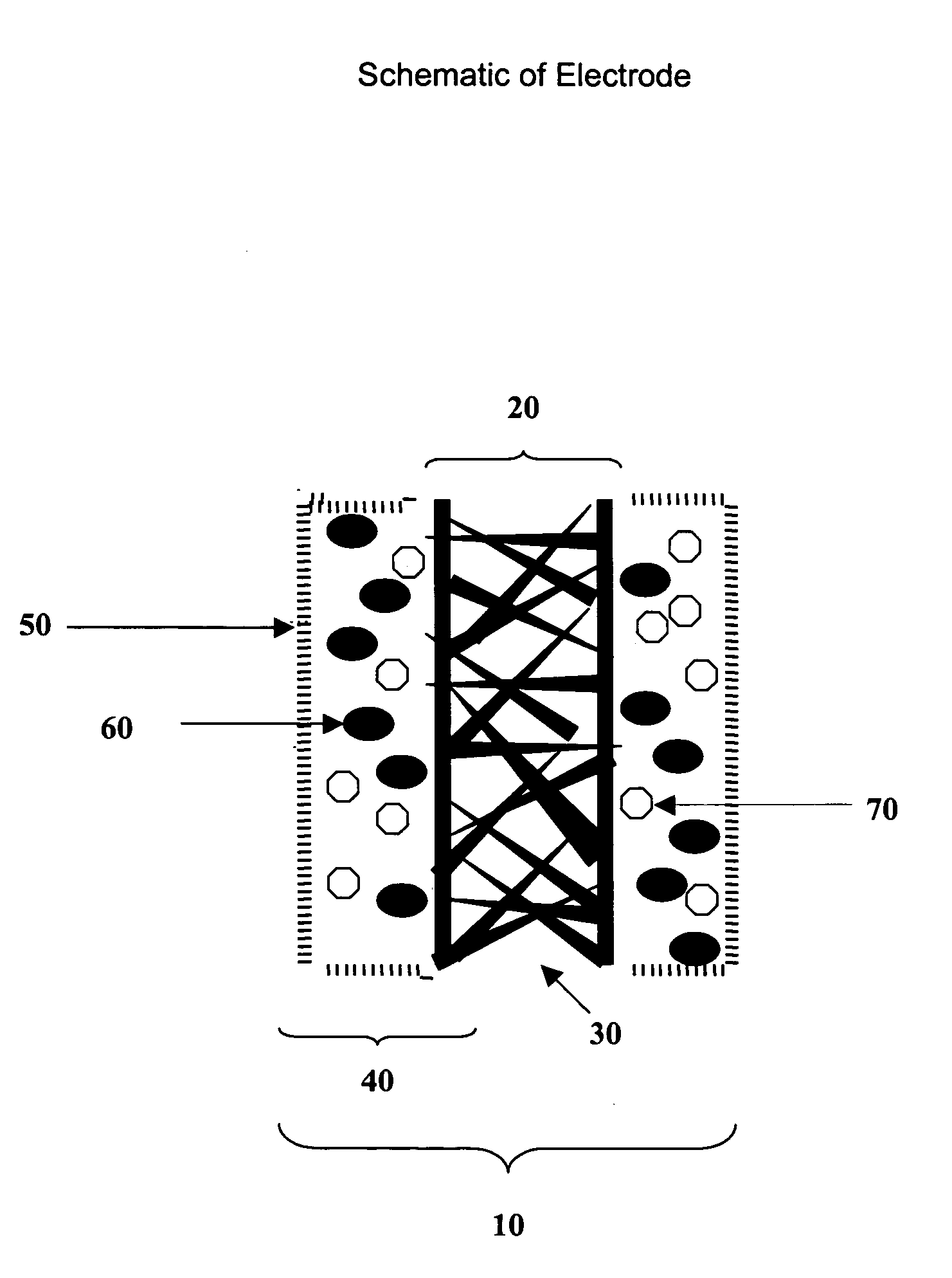
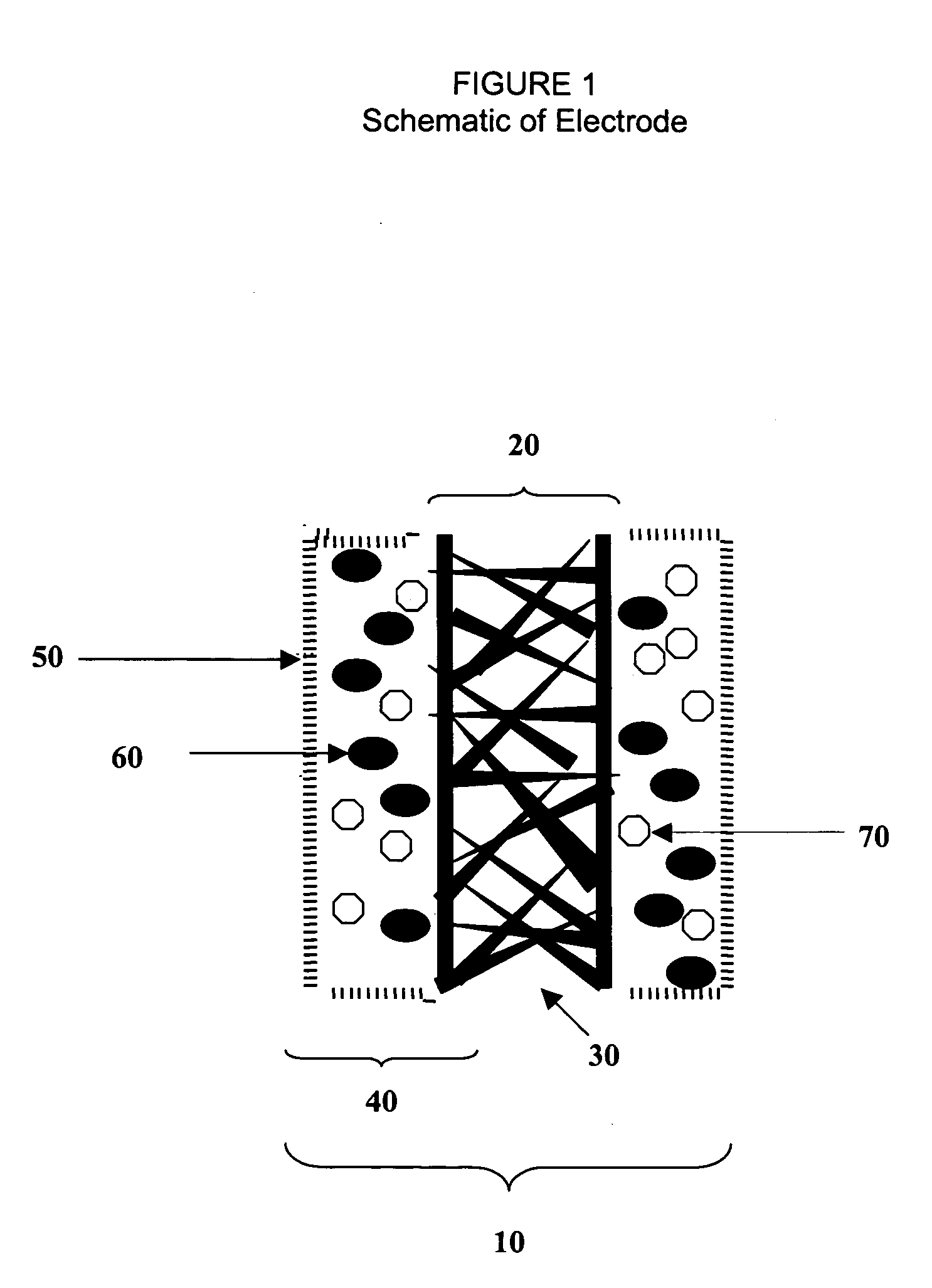
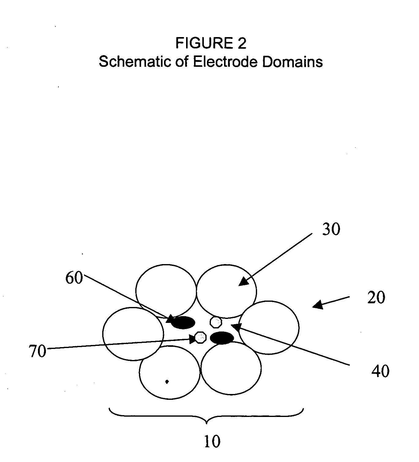
Fuel cell electrode
a fuel cell and electrode technology, applied in the field of fuel cell electrodes, can solve the problems of inability to directly contact the electrode with the redox enzyme, inability to renew and re-energize, and high price of metals, and achieve the effect of suitable results
- Summary
- Abstract
- Description
- Claims
- Application Information
AI Technical Summary
Benefits of technology
Problems solved by technology
Method used
Image

Examples
example 1
Laccase Cathodes With Various Containment Materials
This example demonstrates the construction of a variety of laccase electrodes, wherein the current collector was carbon paper and the containment material was silica or colloidial carbon.
Silica As Containment Material
Laccase solution (12 μl) was applied to the bottom portion of a strip of Toray carbon paper (360 μm thick, 6 mm wide and 7 cm long). After drying, 24 μl of 20 mM ABTS in 50 mM pH 3 phosphate buffer was added to the same area as the laccase and dried. The applied portion of the paper was dipped into a stirred mixture of 200μl 50 mM pH 3 phosphate buffer and 2 mL of tetramethoxysilane. The dipped paper was cured in a chamber at nearly constant 100% humidity for 2 days.
The activity of the electrode was tested by immersing the electrode in 28 mL of 50 mM pH 3 phosphate buffer electrolyte and 1 mM ABTS. Also immersed were a SCE reference electrode and a Pt coil counter electrode. All of these components were connecte...
example 3 (
Prophetic)
Optimal Current Density
In order to construct a cathode that can produce sufficient current density, both the redox catalyst activity and the electrode microstructure should be optimized. Using predictive equations well known in the field (i.e., Ikeda et al., J. Electroanal. Chem. 2001, 496:69-75 and Anal. Sci. 2000, 16:1013), it can be shown that a cathode in which a microporous current collector incorporates microdomains of laccase and ETM in fluid association can be constructed wherein the current collector is capable of producing in excess of 100 mA / cm2 of external surface area. For the modeling, laccase of the type used in the above examples is used as redox catalyst, with values of kcat, KM and KS as measured for this enzyme in homogeneous buffer solution. The electron diffusion coefficient for the ABTS ETM (Palmore et al., J. Electroanal. Chem. 1999, 464:110-117) is as measured in homogeneous buffer solution, as well as the standard diffusion coefficient for oxygen...
example 4
Laccase Cathodes With Various Domain Matrices
This example demonstrates the construction of laccase electrodes having various domain matrices (i.e., of gold nanoparticles, carbon particles and silver particles, respectively).
Following preparation of each porous domain matrix (infra), the matrix was connected to a standard flat conducting working electrode using double-sided conducting carbon tape, where the tape completely covered the original electrode. Control experiments with the tape itself did not lead to significant catalytic currents.
Electrochemistry was carried out in 50 mM pH 3 phosphate buffer using laccase enzyme (15 μl in 2 mL) and recrystallized ABTS (0.25 mM) as the ETM. Oxygen was continually bubbled through the solution, to stir the solution and provide an oxygen-saturated solution. Catalytic current was measured; this current was produced due to the reduction of ABTS, which in turn reduced laccase, which then reduced oxygen at 0.2 V.
Domain Matrix Of Gold Nano...
PUM
| Property | Measurement | Unit |
|---|---|---|
| Length | aaaaa | aaaaa |
| Length | aaaaa | aaaaa |
| Length | aaaaa | aaaaa |
Abstract
Description
Claims
Application Information