Optical network monitor

a network monitor and optical network technology, applied in the field of optical network monitors, can solve the problems of degrading the signal to noise ratio (snr) of other channels, not having the needed snr to carry traffic, and degrading some or all transmissions

Inactive Publication Date: 2005-04-14
LUMENTUM OPERATIONS LLC
View PDF19 Cites 47 Cited by
  • Summary
  • Abstract
  • Description
  • Claims
  • Application Information

AI Technical Summary

Benefits of technology

[0022] It is an object of the present invention to provide the ability to simultaneously process optical channels dispersed from an optical signal in parallel.

Problems solved by technology

For example, a change of the power of an added channel may degrade Signal to Noise Ratio (SNR) of other channels, or alternately, a rerouted wavelength may not have the needed SNR to carry traffic if injected into routes that do not have ample safety margins.
Alternatively, environmental conditions or damage to the fiber cable may degrade some or all transmissions.
If the wavelength drifts beyond its specifications, which are very tight for 50 GHz channel spacing, it contributes to cross talk and its failure, as well as neighboring channels.
However, moving parts, as in the direct-drive motor system for grating tuning, generally make the mechanism sensitive to vibrations and shock.
The moving detector also slows the data acquisition and integration cycles.
In the case of multiple wavelengths, counting fringes is insufficient to extract their spectral profile.
However, PZTs are inherently prone to drift causing these peaks to also drift.
The spectral transmission characteristic of FPls has, however, a limited rejection for wavelengths adjacent to the peak, which limits the dynamic range and SNR measurements.
None of the above described systems suggest how to implement a solid state design without increasing the response time of the device or limiting the wavelength range monitored by the device, nor how to process the channels of the signal in parallel to provide simultaneous processing of the channels.

Method used


Image

  • Optical network monitor
  • Optical network monitor
  • Optical network monitor

Examples


Embodiment Construction

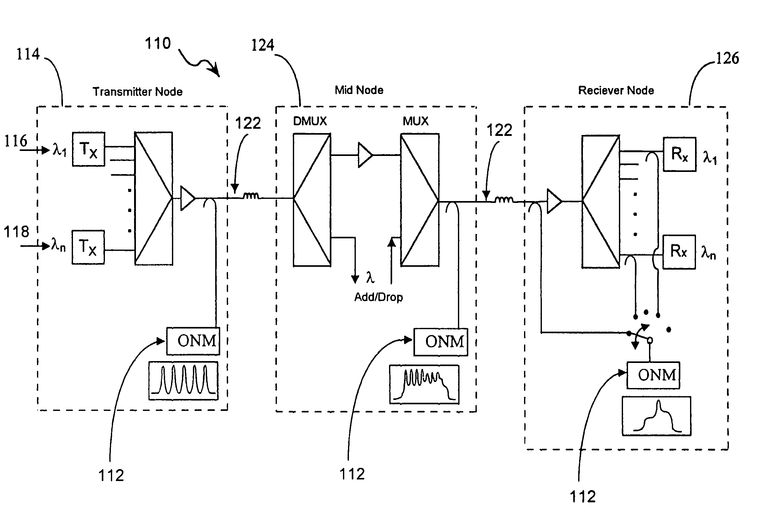
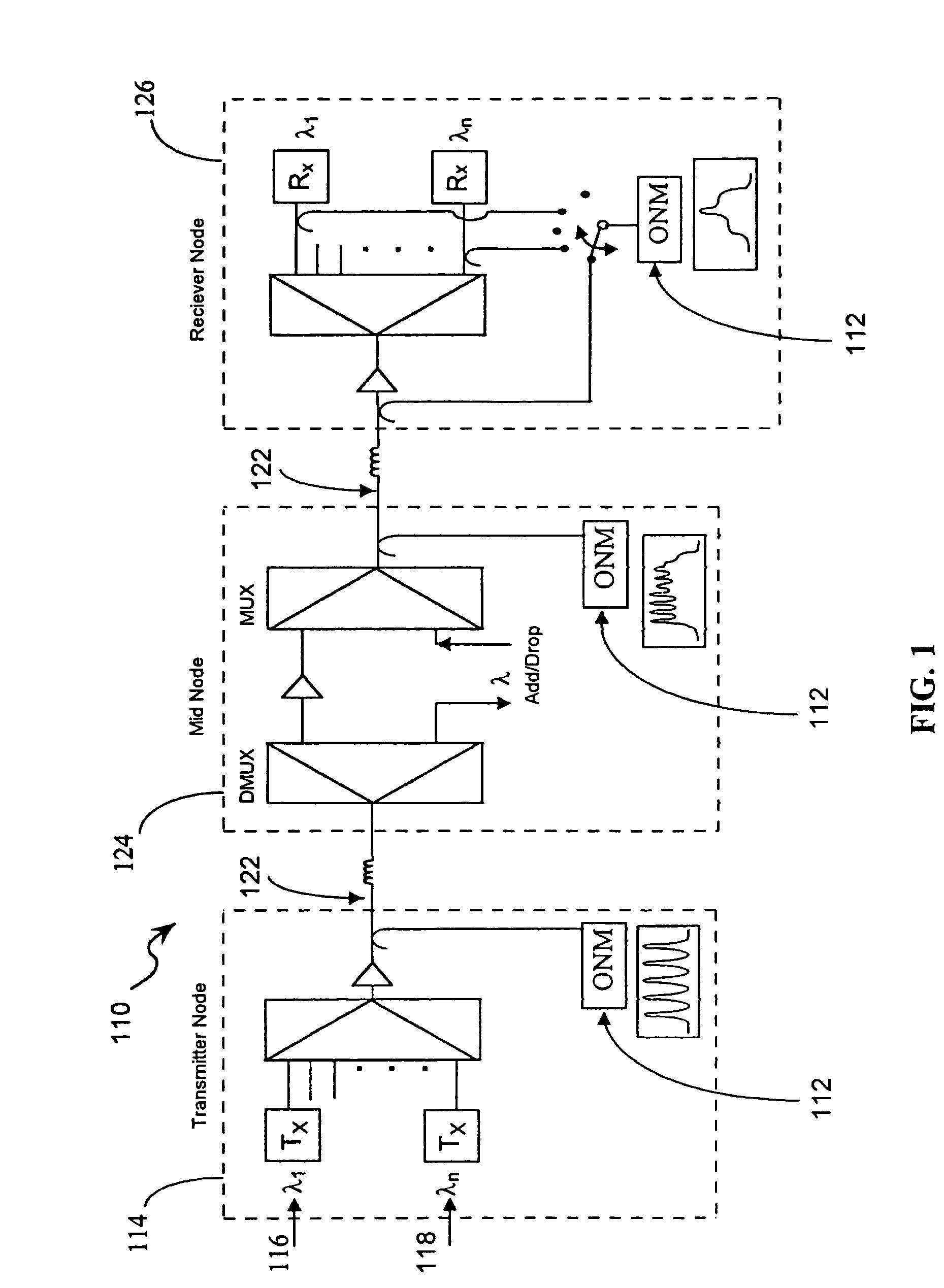
[0043] The present invention is directed to providing an optical spectrometer or optical network monitor that examines the spectral content of a signal from an optical fiber and relays the information to operators of optical networks or to other interested parties. More preferably, the present invention is designed to examine the spectral content of DWDM networks. The input to the spectrometer is usually a tap off a fiber optical communication line that is carrying multiple channels, each at designated wavelengths. The output of the spectrometer includes data arrays that define the channels present and also includes measurements and calculations that are related to channel parameters.

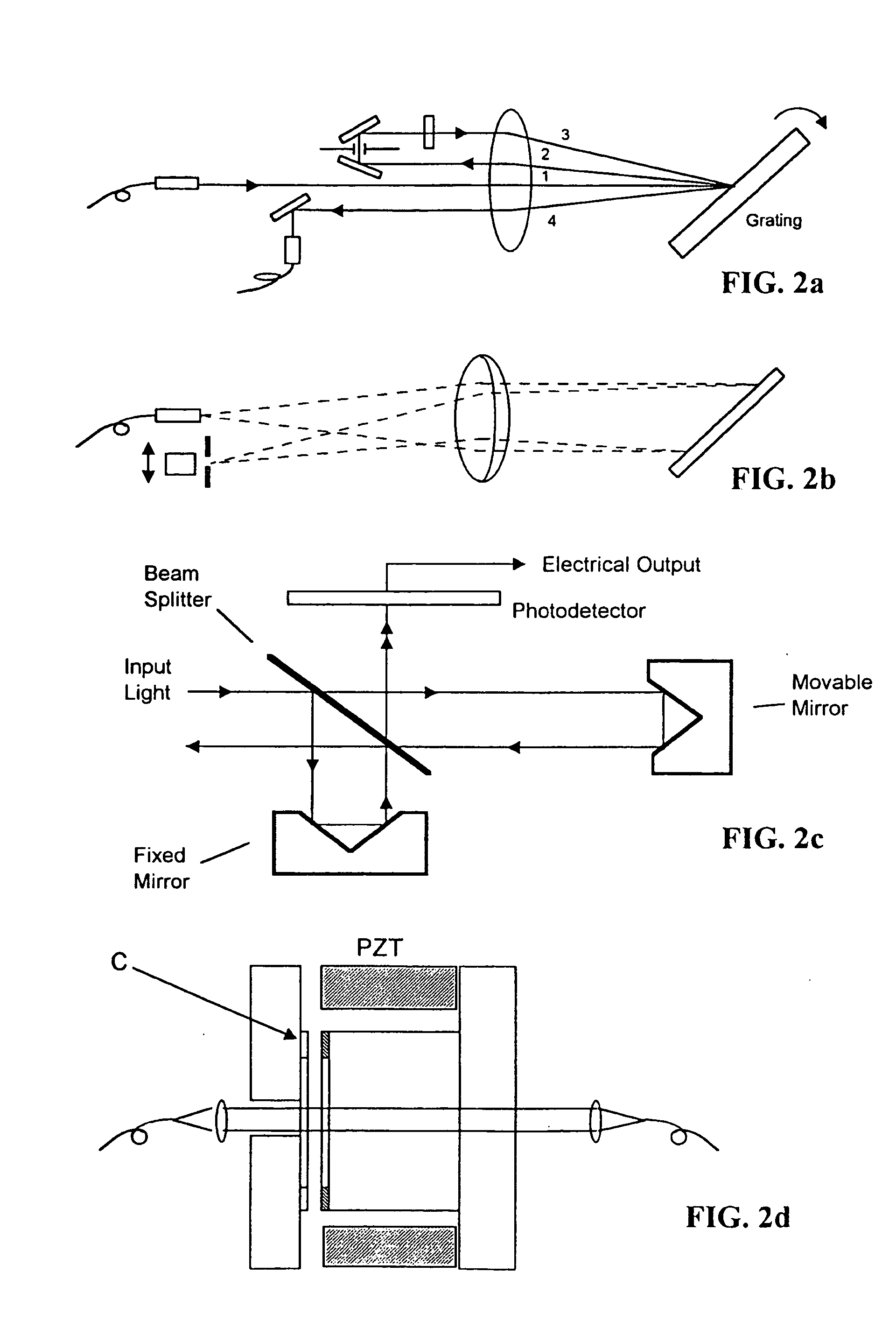
[0044] The network monitor configuration is based on the combination of an input fiber, grating, mirrors, and a linear detector array in a solid state module that has no moving parts. This optical module is coupled to a processor card that processes the information using internal algorithms particular ...


PUM


Abstract

An optical network monitor and a method for monitoring the optical signals of an optical network including a spectrograph that includes a detector array, a processor and outputs. The network monitor receives an optical input signal which includes individual channels. The optical signal is transmitted onto the spectrograph which disperses the optical signal into the individual channels. The individual channels are directed onto the detector array so that the channels are spaced across the detector array. The detector array detects the channels in parallel and transmits to the processor channel parameter data which is processes the parameter data through internal algorithms to produce the outputs.

Description

BRIEF DESCRIPTION OF THE INVENTION [0001] This invention relates generally to an optical network monitor, and more particularly to a network monitor wherein the network is a Dense Wavelength Division Multiplexing network. BACKGROUND OF THE INVENTION [0002] Dense Wavelength Division Multiplexing (DWDM) is the accepted solution for increasing telecommunication network capacity, while controlling overall system cost. Currently, there are several manufacturers that offer multi-wavelength WDM systems using channel rates up to 10 GB / S. Some of these systems are scalable up to 400 GB / s at 0.4 nm channel spacing. [0003] The wavelength allocations for the systems in deployment today all follow the ITU recommendation of 193.1 THz±100 GHz. Currently, manufacturers offer a variety of channel spacing such as 200 GHz (1.6 nm), 100 GHz (0.8 nm), and 50 GHz (0.4 nm). [0004] The high bandwidth of the optical fiber, as well as the bandwidth of erbium-doped fiber amplifiers, enable DWDM. Amplifier ban...

Claims


Application Information

Patent Timeline
Patent Type & Authority Applications(United States)
IPC IPC(8): G01J3/36H04B10/08H04J14/02H04Q11/00
CPCG01J3/36H04B10/077H04B10/07955H04J14/02H04Q2011/0083H04J14/0221H04Q11/0062H04Q2011/0049H04J14/0201
Inventor HENDOW, SAMI T.
Owner LUMENTUM OPERATIONS LLC
Why Eureka
Try Eureka