Heat conduction pipe externally covered with fin member

a technology of heat exchange pipe and fin member, which is applied in the direction of pipe heating/cooling, mechanical equipment, lighting and heating apparatus, etc., can solve the problems of easy damage of the anti-corrosion coating layer on the surface of the metal pipe, corrosion residence, and difficulty in improving heat exchange efficiency among fluids mutually flowing, so as to improve the thermal conductivity through the resin coating layer between the metal pipe and the fin member, the effect of increasing the heat exchange area and increasing the heat radiation property

Active Publication Date: 2005-04-21
USUI KOKUSAI SANGYO KAISHA LTD
View PDF6 Cites 16 Cited by
  • Summary
  • Abstract
  • Description
  • Claims
  • Application Information

AI Technical Summary

Benefits of technology

[0010] To solve aforementioned problems, it is an object of the invention to prevent a fin member from buckling where the fin member is spirally wound on an outer circumference of a metal pipe, to obtain a heat conduction pipe superior in thermal exchange efficiency by enhancing a connectivity between the fin member and the metal pipe to increase thermal conductivity thereof. It is another object of the invention to make manufacturing process of the heat conduction pipe easy by a buckling prevention effect of the fin member and to improve productivity. Furthermore, it is yet another object to maintain great heat exchange efficiency by increasing corrosion resistance and shock resistance and by improving durability of the heat conduction pipe.
[0027] With this invention structured like the above, in a state of a side end surface of the fin member encroaching the surface of the resin coating layer formed on the outer circumference of metal pipes, e.g., steel pipes, aluminum pipes, or the like, the fin member is spirally wound to be well prevented from buckling for strengthening fitness between the fin number and the metal pipe, so it is possible to form adherently the fin member and the metal pipe as stabilized each other with preventing occurrence of a gap between the metal pipe and the fin member. Therefore, the thermal conductivity though the resin coating layer between the metal pipe and the fin member can be improved. Heat exchange area is enlarged by forming the metal fin member, so that. the heat conduction pipe even using the resin material can obtain equal or greater heat radiation property and endothermic property than those of a product solely made of metallic material, and therefore, the heat conduction pipe superior in heat exchange performance can be obtained.
[0028] The fin member encroaches the resin coat layer as secured each other to prevent the fin member in a spiral shape from buckling owing to resilient force of the metallic material, so operation for forming the fin member to the metal pipe can be easily made, whereas the productivity can be improved while the durability for, e.g., vibration of the heat conduction pipe or fluid pressure of the fluid flowing through the outer circumference of the heat conductor, is also improved, whereas the great heat exchange performance can be maintained. Because the resin coat layer is formed, the shock resistance for the bounding stones and the corrosion resistance for rain water, mud, or the like can be increased, so that the great thermal exchange performance of the heat conduction pipe can be maintained.
[0029] By using the heat conduction pipe having the great heat exchange performance like the above, the heat conduction pipe can enjoy the improved property such as endothermic property and heat radiation property of fluid cooling pipes in automobiles and construction machines, air conditioners-for regulating temperature and humidity of residential space, and in various pipes, and enjoy the improved property of the heat exchange performance, the corrosion resistance, heat resistance, and the durability of multi-tubular thermal exchangers for general industry, heaters, hot water supply, or the like while manufactured at a low cost.

Problems solved by technology

JA-8-188884 and JA-10-315295, however, has a problem in terms of the heat radiation property and the endothermic property thereof because the resin coating layer is thickly formed for improving shock resistance and the corrosion resistance, so it is difficult to improve heat exchange efficiency among fluids mutually flowing though the interior and exterior of the heat conduction pipe.
JA-9-42573, JA-9-136111, and JA-11-325778, on the other hand, it is possible to obtain high heat exchange efficiency owing to the enlarged heat exchange area, but the anticorrosion plating layer on the surface of the metal pipe is easily damaged due to, e.g., the bounding stones, so there rises a problem with the corrosion residence.
Furthermore, the fin member made of the metallic material in a flat plate shape having a contact portion, is formed in a spiral shape and wound on the metal pipe, and therefore, spiral buckling is occurred due to resilient force of the metallic material as formed with wave form edges at the contact portion thereof in contact with the metal pipe, so that adhesion between the fin member of the contact portion and the outer circumferential surface cannot be done in a good manner, so that good thermal conductivity between the metal pipe and the fin member cannot be obtained.
To prevent the buckling phenomenon from occurring, both side end surfaces of the fin member in the spiral shape are secured to the metal pipe by clips, screws, or the like, but manufacturing process takes many steps, and further, the connection between the fin member and the metal pipe by the above-described process is not enough.
A gap between the fin member and the metal pipe, therefore, needs to be plugged by, e.g., coating or brazing, so that the operation process is so complicated and that it is difficult to improve the productive efficiency.

Method used


Image

  • Heat conduction pipe externally covered with fin member
  • Heat conduction pipe externally covered with fin member
  • Heat conduction pipe externally covered with fin member

Examples


first embodiment

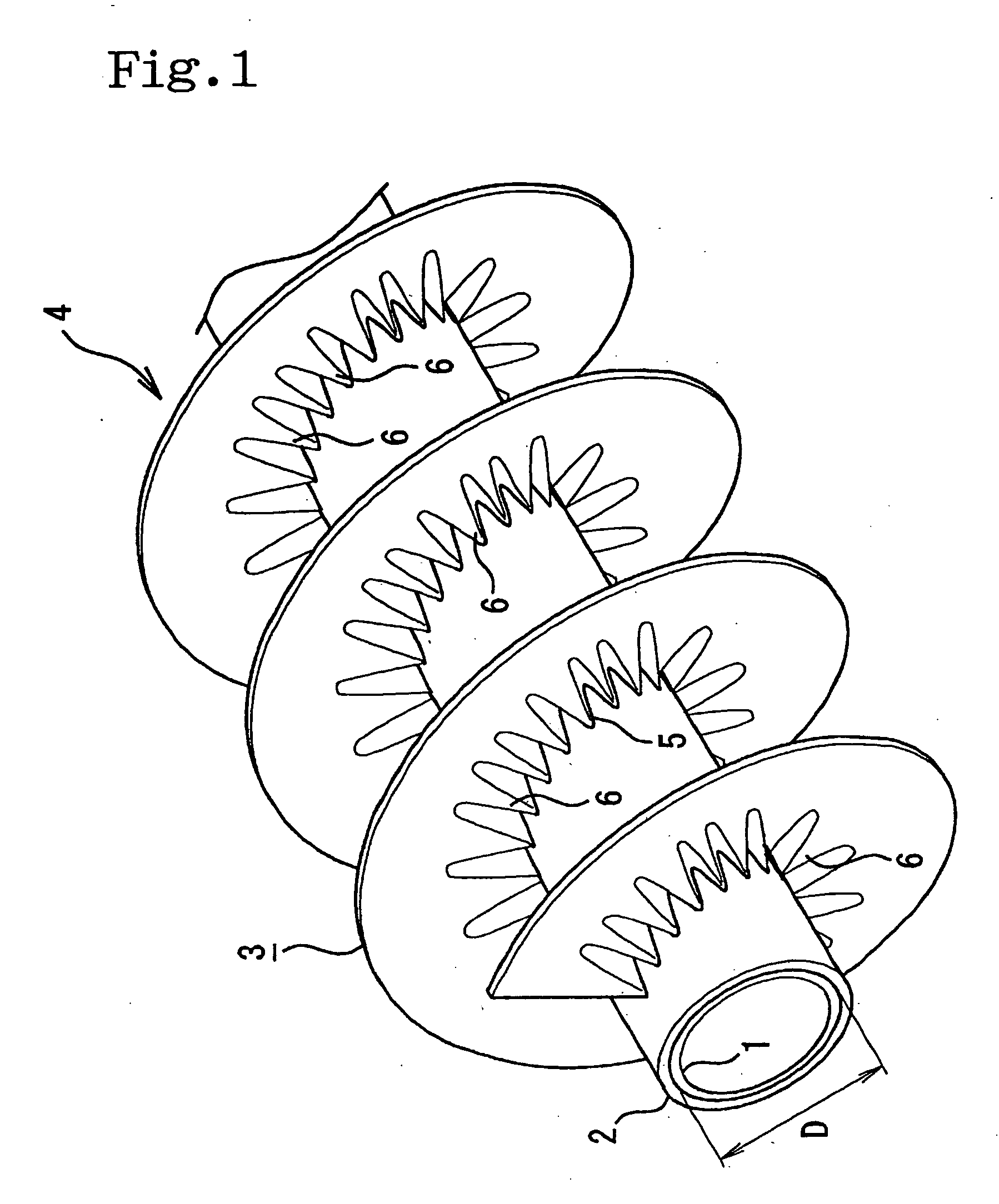
[0055] The first embodiment shown in FIG. 1 to FIG. 4 is described in detail. Numeral 1 is a metal pipe using, e.g., a single-wound pipe having an outer surface not covered with copper, a double-wound pipe having the outer surface covered with the copper, an aluminum pipe, or the like, wherein an outer diameter is defined as 8 mm and thickness is defined as 0.7 mm. The metal pipe 1 can obtain corrosive resistance by being covered with a resin coating layer 2 as described hereinafter, so the metal pipe can be directly used. In this embodiment, however, sacrificially corrosive anticorrosion plating (not shown in Figures) is further formed on the outer surface of the metal pipe, so the great corrosion resistance can be obtained under harsh corrosive environment.

[0056] The anticorrosion plating is formed of one layer by coating, e.g., zinc, tin, alloy of tin and zinc, nickel, alloy of zinc and nickel, alloy of zinc and aluminum, or may be structured of a plurality of the layers, e.g., ...

second embodiment

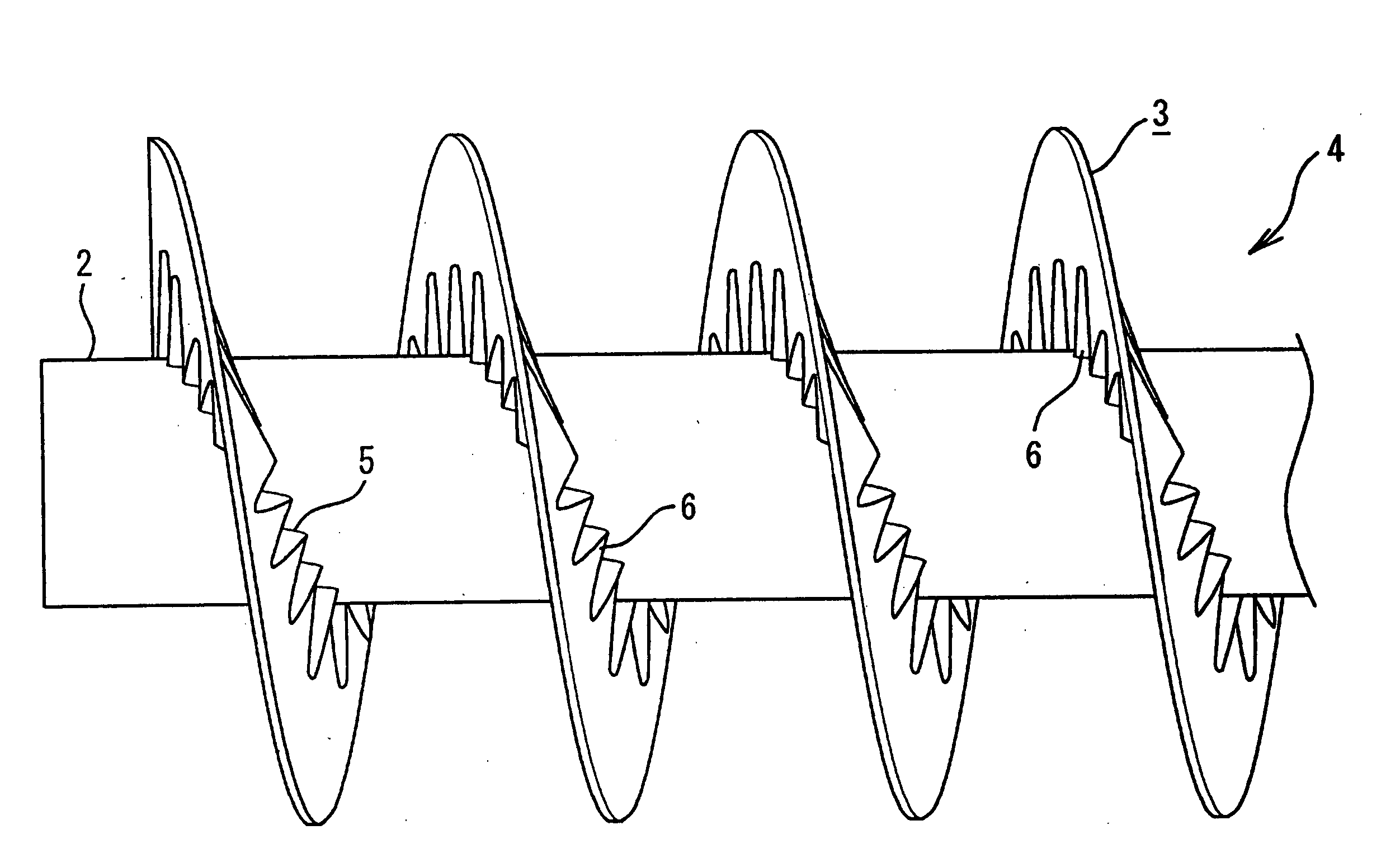
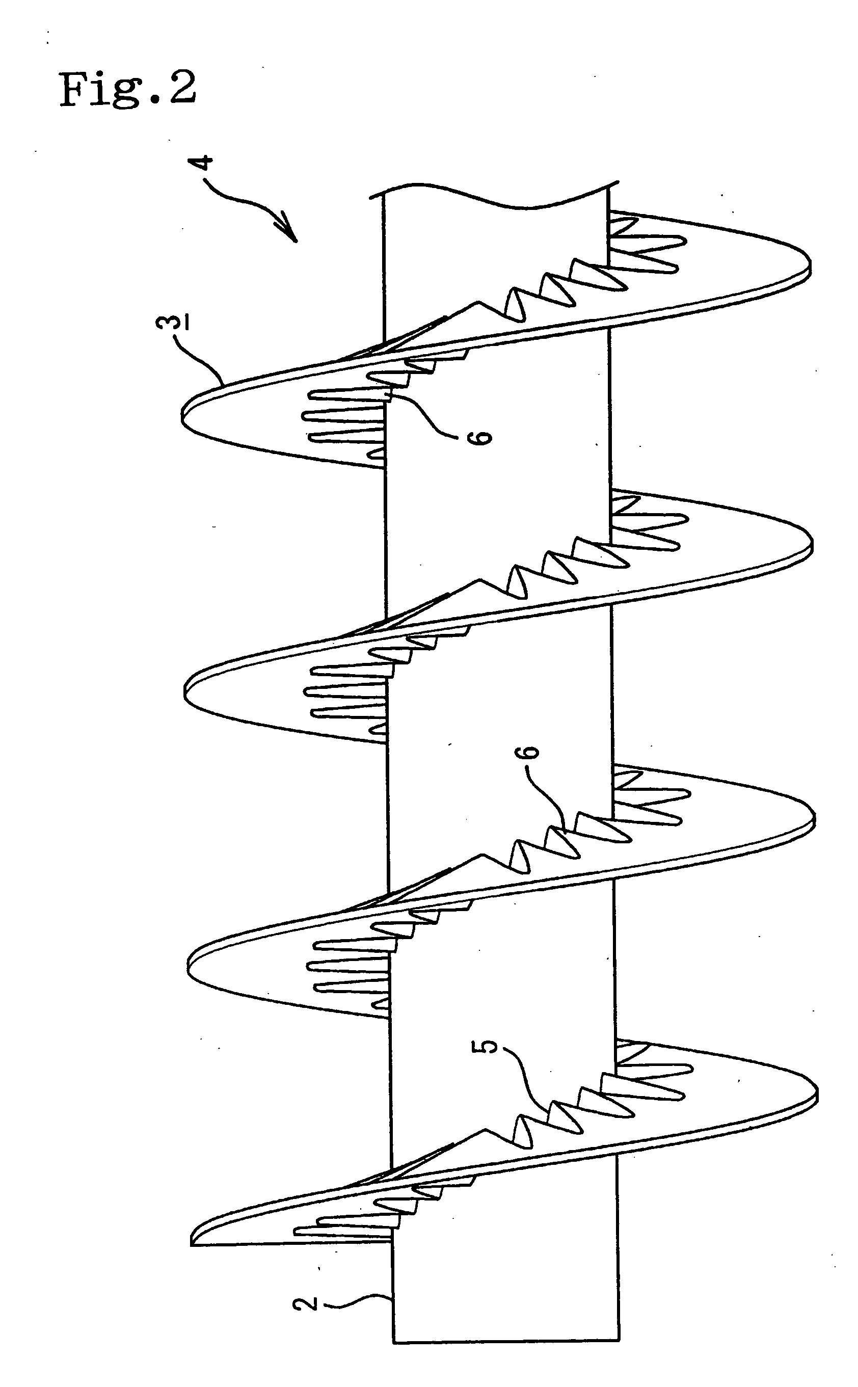
[0073] In the above described first embodiment, immediately before the fin member 3 holding wave form edges over the whole width is formed on the metal pipe, in order to make spiral winding of the fin member on the outer circumference of the metal pipe 1 easy, the inner circumferential side is radially reduced to enlarge the undulation of the wave form edges 6 while the wave form edges 6 are expanded flatly at the outer circumferential side, so the fin member 3 is curved in an arc shape. In the second embodiment, on the other hand, as shown in FIG. 6, in a state where the fin member 3 holding a plurality of the wave form edges 6 over the whole wide is spirally wound on the metal pipe 1, the undulation of the wave form edges 6 is enlarged by shrinking the inner circumferential side while at the outer circumferential side, as shown in FIG. 6, the wave form edges 6 stay as just opened without being expanded flatly, so the wave form edges is formed at the outer circumferential side in a...

third embodiment

[0078] In the embodiment 3 shown in the FIG. 7, cathodic electrodeposition coating is arranged on the whole external surface of the heat conduction pipe. The process of manufacturing the heat conduction pipe 4 is first subject to zinc based plating on the outer circumference of the metal pipe 1 made of iron to enhance the corrosion resistance, and after arranging an epoxy resin on the outer circumference as a primer, a PA is extruded on the outer circumference of the epoxy resin to form the resin coating layer 2. The heat conduction pipe 4 is-formed by spirally arranging the metal fin member 3 with zinc based plating to enhance the corrosion resistance on the outer circumference of the metal pipe 1 having the resin coating layer 2. The spiral arrangement of the fin member 3 may be arranged by tensioning the outer circumference side as shown in the First embodiment in the FIG. 5 when the fine member 3 formed with the wave form edges 6 across whole width as shown in the FIG. 4 to the ...


PUM

PropertyMeasurementUnit
thicknessaaaaaaaaaa
thicknessaaaaaaaaaa
thicknessaaaaaaaaaa

Abstract

It is an object of this invention to obtain a heat conduction pipe superior in corrosion resistance as well as heat exchange efficiency between fluid flowing respectively through an inside and an outside for great heat radiation property and endothermic characteristics. It is also object of this invention to form the heat conduction pipe superior in the corrosion resistance as well as the heat radiation property and endothermic characteristics at inexpensive price. To achieve the above, at least single resin coating layer is formed on an outer circumferential surface of a metal pipe, a metal fin member is spirally wound on an outer circumferential surface of the resin coating layer with a side end surface the metal fin member in contact. The winding contact portion is made to encroach a surface of the resin coating layer to form the heat conduction pipe.

Description

BACKGROUND OF THE INVENTION [0001] 1. Field of the Invention [0002] This invention relates to a heat conduction pipe having a corrosion resistance used in fluid cooling pipes of automobiles and construction machines, air conditioners for regulating temperature and humidity of residential space, or the like under corrosive environment, and further is to obtain a heat conduction pipe that can exchange effectively heat according to great heat radiation property and endothermic property thereof as well as superiority in a corrosion resistance. [0003] 2. Description of Related Art [0004] Conventionally, as a heat conduction pipe having corrosion resistance, some metal pipes such as described in Japanese Patent Application Publication Nos. JA-8-188884 and JA-10-315295 has existed, e.g., steel pipes or aluminum pipes hold anticorrosion plating, e.g., zinc plating or a chromate film; thermoplastic resin coating layer, e.g., polyamide (PA), polyptopylene (PP), polyethylene (PE), or the like ...

Claims


Application Information

Patent Timeline
Patent Type & Authority Applications(United States)
IPC IPC(8): F16L9/00F16L53/00F28F1/10F28F1/32F28F1/36F28F13/18F28F19/04F28F21/06F28F21/08
CPCF16L9/006F28F19/04F28F13/185F28F1/36F28F1/10F28F1/32
Inventor HASHIMOTO, YASUAKIYOTSUMOTO, SHU
Owner USUI KOKUSAI SANGYO KAISHA LTD
Why Eureka
Try Eureka