In this case, the collector resonating circuit and the
resonance circuit present in the primary circuit interfere with each other, making it very difficult to adjust the circuit constant.
In either case, those inverter circuits are each designed merely in such a way that multiple small high efficient inverter circuits are laid out in proportion to the number of cold-cathode fluorescent lamps, and are thus complicated.
It is the step-up transformer and the drive circuit in the inverter circuit for a high-power surface
light source that require the cost most, so that the required use of the step-up transformer and the drive circuit causes the overall cost for the inverter circuit to increase.
While it is necessary to achieve cost reduction for an inverter circuit for discharge lamps by reducing the number of step-up transformers and drive circuits by making the power of the step-up transformers greater, it is difficult to drive cold-cathode fluorescent lamps in parallel.
In an inverter circuit for discharge lamps, like cold-cathode fluorescent lamps, which require a
high voltage, it is very difficult to make the power of the step-up transformer higher for the following reason.
This naturally increases the thickness of the transformer, which is not allowed to become too thick due to the particular demand of designing
liquid crystal display backlights thinner besides compactness.
Because the shape of the transformer greatly influences the parameters thereof and the relationship between the cross-sectional area of the magnetic path and the length of the magnetic path should be kept at a constant ratio, however, the shape of the transformer does not have a high degree of freedom.
It is very difficult to design a flat and high-power transformer.
The current phase of the portion of the secondary winding which is far from the primary winding is delayed from the current phase of the primary winding, so that a large portion of flux leaks from the secondary winding, thus forming a
loose coupling portion.
When the self-resonance frequency becomes lower than the operational frequency of the inverter, the transformer gradually loses the step-up operation.
That is, it is the conventional knowledge that the
transformation ratio should simply be increased to
gain the step-up ratio, so that an insufficient step-up ratio when pointed out is coped with winding the secondary winding more.
This measure however leads to excessive winding of the secondary winding, which often results in a lower self-resonance frequency of the secondary winding.
This results in a vicious circle of suppressing the step-up ratio more.
Therefore, there is a limit to increasing the number of sections.
Needless to say, designing the transformer is difficult.
As a result, the leakage flux on the secondary winding does not become uniform, disabling the achievement of the ideal conditions to ultimately minimize the core loss.
However, with a requirement of a flat shape added to the difficult requirement that three conditions of the
leakage inductance, the speed of the
progressive wave (i.e., the self-resonance frequency) and the
characteristic impedance should be met, it becomes harder to design a transformer which satisfies all the conditions at a time.
Generally speaking, however, when transformers with very small flux leakage are connected in parallel, the current may flow between the secondary windings of the transformers and reduce the efficiency or heat may be generated due to variations in the characteristics of the individual transformers.
With insufficient
reactance, the load to be dispersed over the transformers does not become uniform, so that when multiple transformers are connected, the load is concentrated on some transformers.
The transformers to be used in this case have a small
leakage inductance and are of course unsuitable for parallel connection.
To acquire parallel connection of transformers having small leakage
inductance, therefore, a practical inverter circuit is difficult to design unless the parallel connection is made via
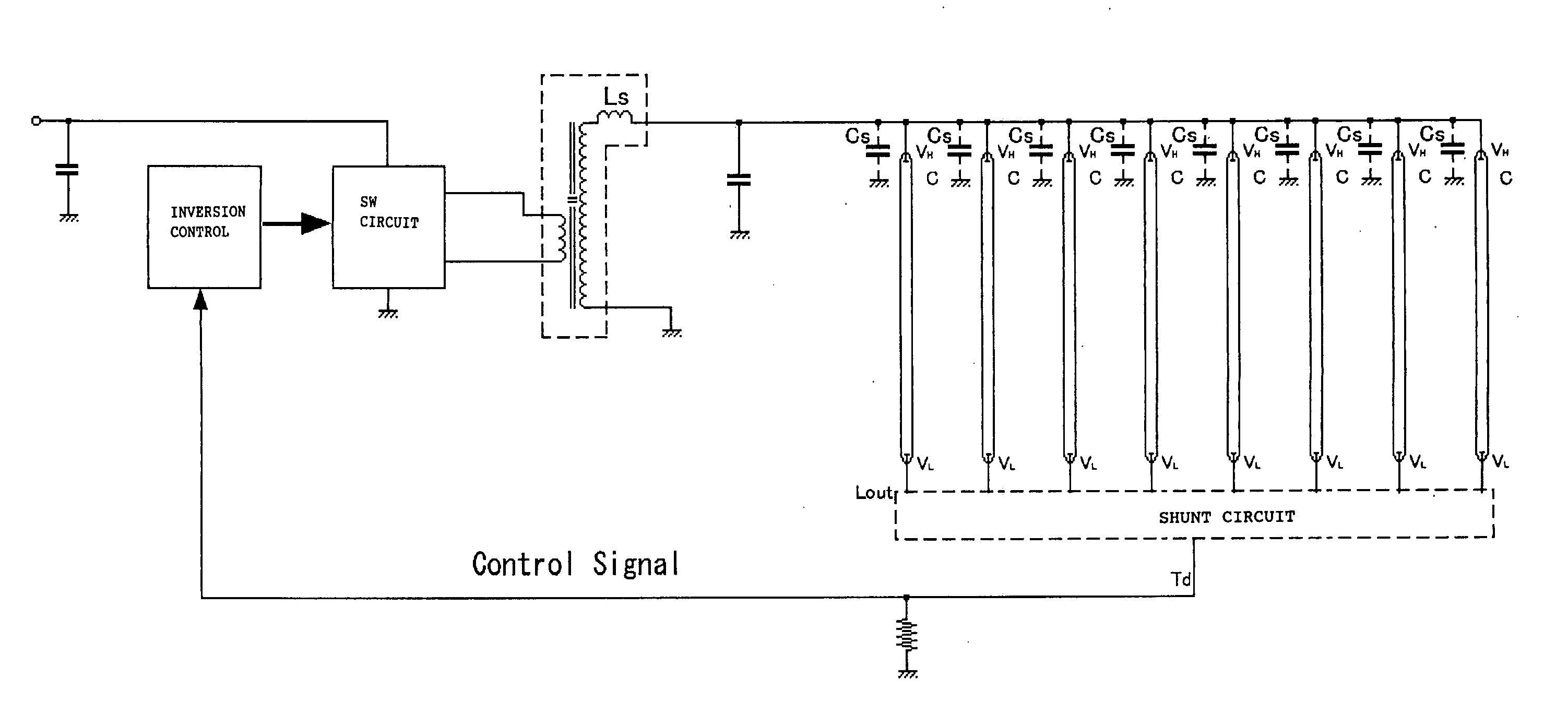
ballast capacitors as shown in FIG. 20.

