Micromirror having reduced space between hinge and mirror plate of the micromirror

a technology of mirror plate and micromirror, which is applied in the field of microelectromechanical systems, can solve the problems of large spatial light modulator, but not cost-effective, and achieve the effects of small overall dimensions, good resolution and optical efficiency, and high resolution and optical efficiency

Inactive Publication Date: 2005-04-28
VENTURE LENDING & LEASING IV +1
View PDF55 Cites 37 Cited by
  • Summary
  • Abstract
  • Description
  • Claims
  • Application Information

AI Technical Summary

Benefits of technology

[0007] In the present invention, both designs of micromirror arrays of spatial light modulators and methods of making the same are provided. The spatial light modulators allow for micromirror arrays having smaller overall dimensions, while allowing for good resolution and optical efficiency. Moreover, the spatial light modulator allows for higher resolutions and optical efficiency while maintaining the same dimension of the micromirror array. In a number of embodiments of the invention, micromirror arrays are constructed having a pitch of 10.16 micrometers or less. In other embodiments, micromirror array designs include micromirror arrays having a gap between adjacent micromirrors of 0.5 micrometers or less, and in other embodiments the gap is from 0.1 to 0.5 micrometer. In yet other embodiments, micromirrors are constructed that do not have symmetric ON and OFF positions. In still further embodiments, methods for making mirror arrays utilize spontaneous gas phase chemical etchants to provide mirrors having smaller than usual dimensions.

Problems solved by technology

A large spatial light modulator, however, is not cost-effective due to many factors, such as higher costs in manufacturing and optical elements (e.g. condensing and projection lenses).

Method used


Image

  • Micromirror having reduced space between hinge and mirror plate of the micromirror
  • Micromirror having reduced space between hinge and mirror plate of the micromirror
  • Micromirror having reduced space between hinge and mirror plate of the micromirror

Examples


Embodiment Construction

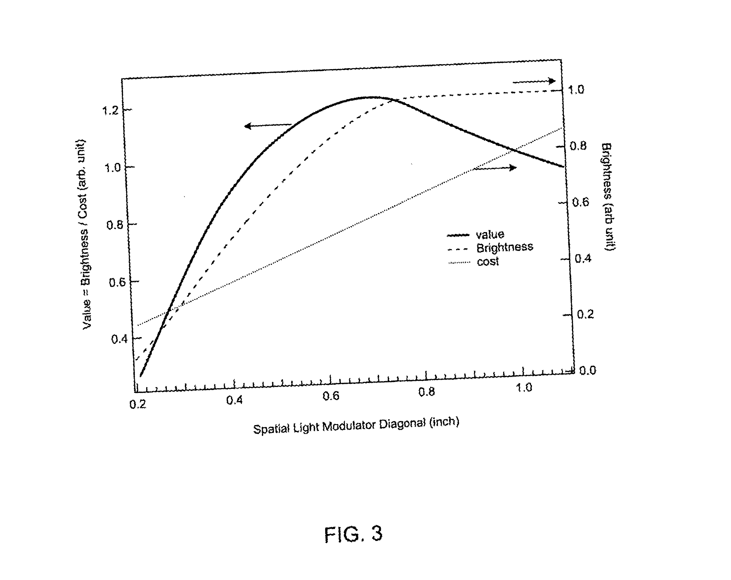
[0030] In the present invention, both designs of micromirror arrays of spatial light modulators and methods of making the same are provided. The spatial light modulators allow for micromirror arrays having smaller overall diameters, while allowing for good resolution and optical efficiency. Moreover, the spatial light modulator allows for higher resolutions and optical efficiency while maintaining the same overall dimensions of the micromirror array of the spatial light modulator.

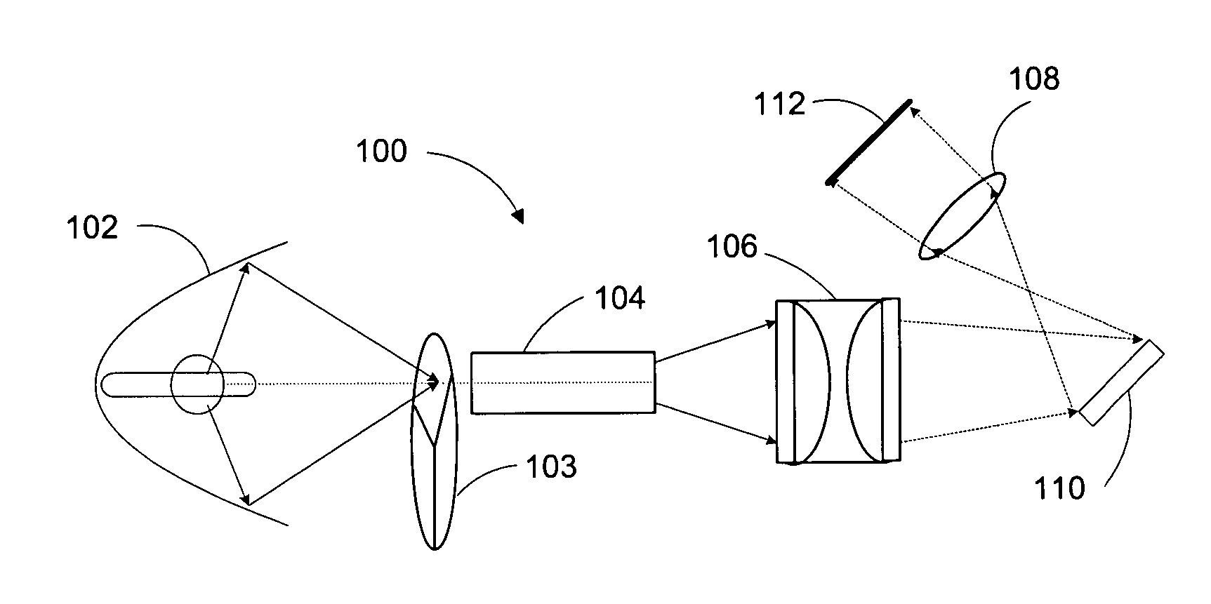
[0031] According to the invention, the light source of the display system is an arc lamp with a short arc length preferably 1.6 millimeters or less, more preferably 1.3 millimeters or less, more preferably 1.0 millimeters or less. The power of the arc lamp is preferably from 100 watts to 250 watts.

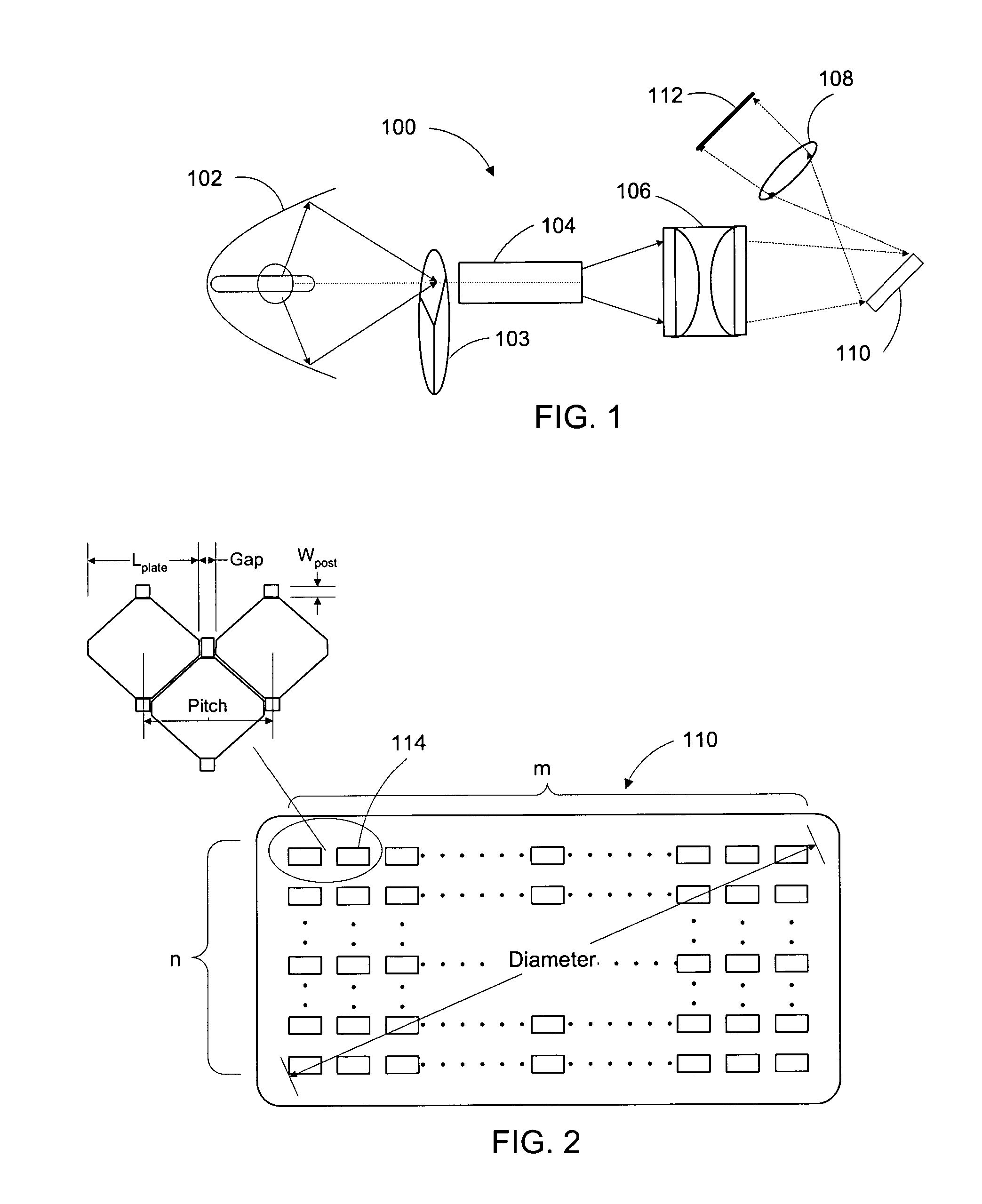
[0032] The dimension of the micromirror array and the spatial light modulator is defined with reference FIG. 2. Spatial light modulator 110 comprises an array of micromirrors that has m×n micromirrors (e.g. micr...


PUM


Abstract

A spatial light modulator is disclosed, along with a method for making such a modulator that comprises an array of micromirror devices. The center-to-center distance and the gap between adjacent micromirror devices are determined corresponding to the light source being used so as to optimize optical efficiency and performance quality. The micromirror device comprises a hinge support formed on a substrate and a hinge that is held by the hinge support. A mirror plate is connected to the hinge via a contact, and the distance between the mirror plate and the hinge is determined according to desired maximum rotation angle of the mirror plate, the optimum gap and pitch between the adjacent micromirrors. In a method of fabricating such spatial light modulator, one sacrificial layer is deposited on a substrate followed by forming the mirror plates, and another sacrificial layer is deposited on the mirror plates followed by forming the hinge supports. The two sacrificial layers are removed via the small gap between adjacent mirror devices with spontaneous vapor phase chemical etchant. Also disclosed is a projection system that comprises such a spatial light modulator, as well as a light source, condensing optics, wherein light from the light source is focused onto the array of micromirrors, projection optics for projecting light selectively reflected from the array of micromirrors onto a target, and a controller for selectively actuating the micromirrors in the array.

Description

TECHNICAL FIELD OF THE INVENTION [0001] The present invention is related generally to the art of microelectromechanical systems, and, more particularly, to micromirror array devices comprising a plurality of micromirror devices for use in display systems. BACKGROUND OF THE INVENTION [0002] The present invention relates to spatial light modulators having reflective micromirrors that are provided within a micromirror array for, e.g., projection-type displays (or for steering light beams, maskless lithography and maskless micro array production). A simplified such display system is illustrated in FIG. 1. In its very basic configuration, display system 100 comprises light source 102, optical devices (e.g. light pipe 104, condensing lens 106 and projection lens 108), display target 112 and spatial light modulator 110 that further comprises a plurality of micromirror devices (e.g. an array of micromirror devices). Light source 102 (e.g. an arc lamp) emits light through the light integrato...

Claims


Application Information

Patent Timeline
Patent Type & Authority Applications(United States)
IPC IPC(8): G02BG02B26/00G02B26/08H01LH01L21/00
CPCG02B26/0841B82Y30/00G02B26/00G02B26/08
Inventor PATEL, SATYADEV R.HUIBERS, ANDREW G.
Owner VENTURE LENDING & LEASING IV
Why Eureka
Try Eureka