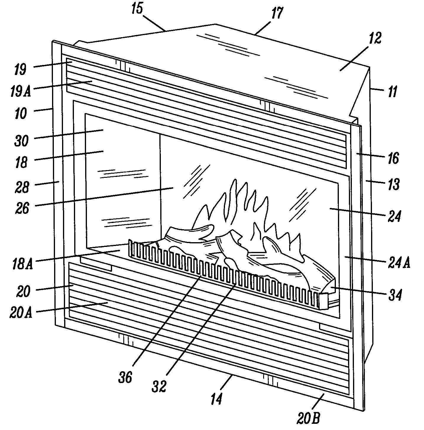
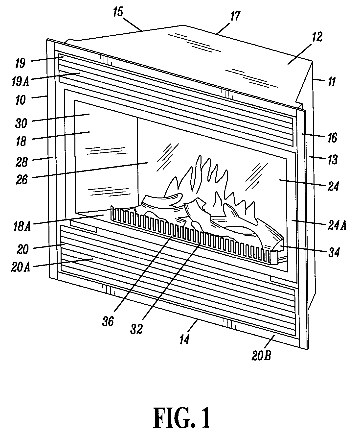
[0014] An additional embodiment includes a screen or privacy glass panel, made of material that has a property of changing the
opacity according to the
electric current applied to it. The privacy glass panel has a high degree of transparency when
electrical current is applied. A controller applies
electrical current to the privacy glass when the fireplace is turned off. This allows the user to see through this glass and have the
visual perception of the logs and
ember bed when the fireplace is off. The privacy glass is cloudy or hazy when no
electrical current is applied. A controller prevents the flow of electrical current to the privacy glass when the fireplace is turned on. The privacy glass can be positioned anywhere inside the fireplace—such as inside the ember-
bed or
imitation logs—because it is nearly invisible to the user when the fireplace unit is off.
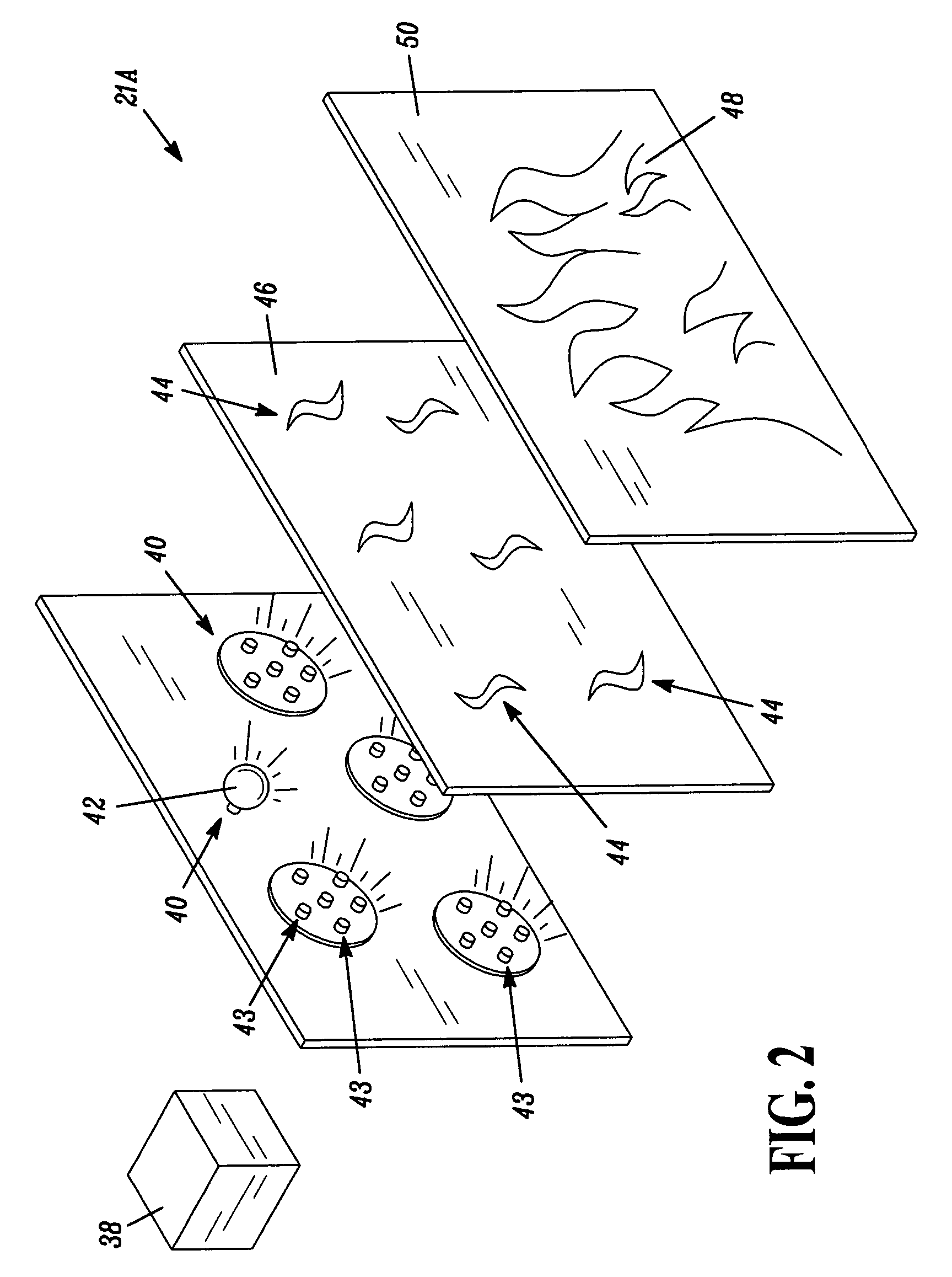
[0015] More specifically, the privacy glass may be made from clear or tinted glass or a glass-like polymeric-based material, such as polycarbonates, through the use of which image of flickering flames is produced that is well defined and realistic. The material used for the privacy glass can be free-forming so that the glass can be manipulated into any shape desired. For example, forming the privacy glass to a three-dimensional shape can create the look of a flame that would appear to be coming from different planes within the ember-bed and / or logs, greatly improving the realism of the
fire effect in the electric fireplaces.
[0018] One embodiment of the refractories includes a surface having at least one face on the surface, to allow
refraction of light in more than one direction. This allows the simulation of a glowing ember bed effect to be viewed from more than one angle from the front of the fireplace. The refractories may include a surface having a plurality of faces positioned around the surface so that light is refracted in a multiple of directions thereby assisting in the ember bed simulation. The refractories may be one single multifaceted bead or a plurality of beads to realistically replicate real bed embers. Refractories that are suitable for this purpose include multifaceted beads made from plastic, glass, or a naturally occurring material; broken pieces of tempered glass; and broken pieces of plastic such as acrylic or
polycarbonate may be used as refractories. The refractories may be clear or
colored including those that are, for example painted with stained glass paint.
[0020] Another preferred embodiment of the present invention uses light emitting diodes, termed LEDs for purposes of this application. A
light emitting diode is any
semiconductor device that emits visible light when an
electric current is passed through it. LEDs can be of varying type such as air gap LEDs, GaAs LEDs and
polymer LEDs. LEDs are
high intensity, energy efficient illumination sources. LEDs, either individually or custom packaged, are commercially available from manufacturers, among others, such as Boca Flasher, Boca Raton, Fla. LEDs produce light in many colors, including, but not limited to, amber, yellow, orange, green, blue and white—further, an individual LED may be designed to change colors, varying from amber to yellow to orange, in response to an electrical
signal. LEDs give off virtually no heat and have a relatively unlimited lifetime, essentially eliminating the need for replacement. The LEDs may comprise a plurality, or cluster, of LEDs. Alternatively, the LEDs may comprise one individual LED. Again, the intensity of the
light source may be varied such as by varying the location and / or number of LEDs. Further, the LEDs can include a textured surface to provide “diffused light”. “Sandblasting” provides such a textured surface.
[0021] Illumination in other embodiments of the present invention may be provided by one or more long-life
halogen light bulbs, incandescent light bulbs, flame based sources, carbon arc
radiation sources, fluorescent sources, luminescent bulbs or induction light bulbs.
Fiber optic cables, or any other material that facilitates the transmission of light, such as acrylic or nylon, may be used to assist in transmitting the visible light.
[0024] Further, as an additional embodiment, a motor driven rotating disk can be positioned between one or more light sources and one or more
fiber optic cable ends. The disk includes apertures, which approximate a series of shutters that fragment the transmission of the visible light as the disk rotates thereby causing the light emitted from the light source to interruptedly enter the
fiber optic cable. By varying the number and location of the apertures in the disk, light of varying brightness may be transmitted through the
fiber optic cable and therefrom to the flame cut-out panel, logs or refractories. The combustion simulation as a result takes on an undulating effect like that seen in fireplaces in which wood is actually burning.

