
Surface-emitting laser diode having reduced device resistance and capable of performing high output operation, surface-emitting laser diode array, electrophotographic system, surface-emitting laser diode module, optical telecommunication system, optical interconnection system using the surface-emitting laser diode, and method of fabricating the surface-emitting laser diode

Active Publication Date: 2005-05-12
RICOH KK
View PDF15 Cites 53 Cited by
  • Summary
  • Abstract
  • Description
  • Claims
  • Application Information

AI Technical Summary

Benefits of technology

[0024] A more specific object of the present invention is to provide a surface-emitting laser diode that has a low device resistance and can perform high-output operations while maintaining single fundamental transverse-mode oscillation with high outputs, a surface-emitting laser diode array that includes the surface-emitting laser diode, an electrophotographic system, a surface-emitting laser diode module, an optical communication system, an optical interconnection system, and a method of fabricating the surface-emitting laser diode.
[0027] Conventionally, a surface-emitting laser diode device has a structure in which one oxidation structure performs both single fundamental transverse-mode control and current restricting. Such an oxidation structure is provided on the hole confining side having a higher carrier restricting efficiency. Between the two types of carriers, holes have lower mobility than electrons. After restriction, holes rarely scatter, and can maintain great confining effects. Also, the diameter or each side of the non-oxide region of the hole restricting structure is only three to five times as long as the oscillation wavelength, so as to suppress high-order transverse-mode oscillation and to achieve single fundamental transverse-mode oscillation. However, as the mobility of holes is low, the confining part of the hole restricting structure is likely to have high resistance. Even if the area of the non-oxide (conductive) region is reduced so as to achieve single fundamental transverse-mode oscillation, the device resistance becomes very high.
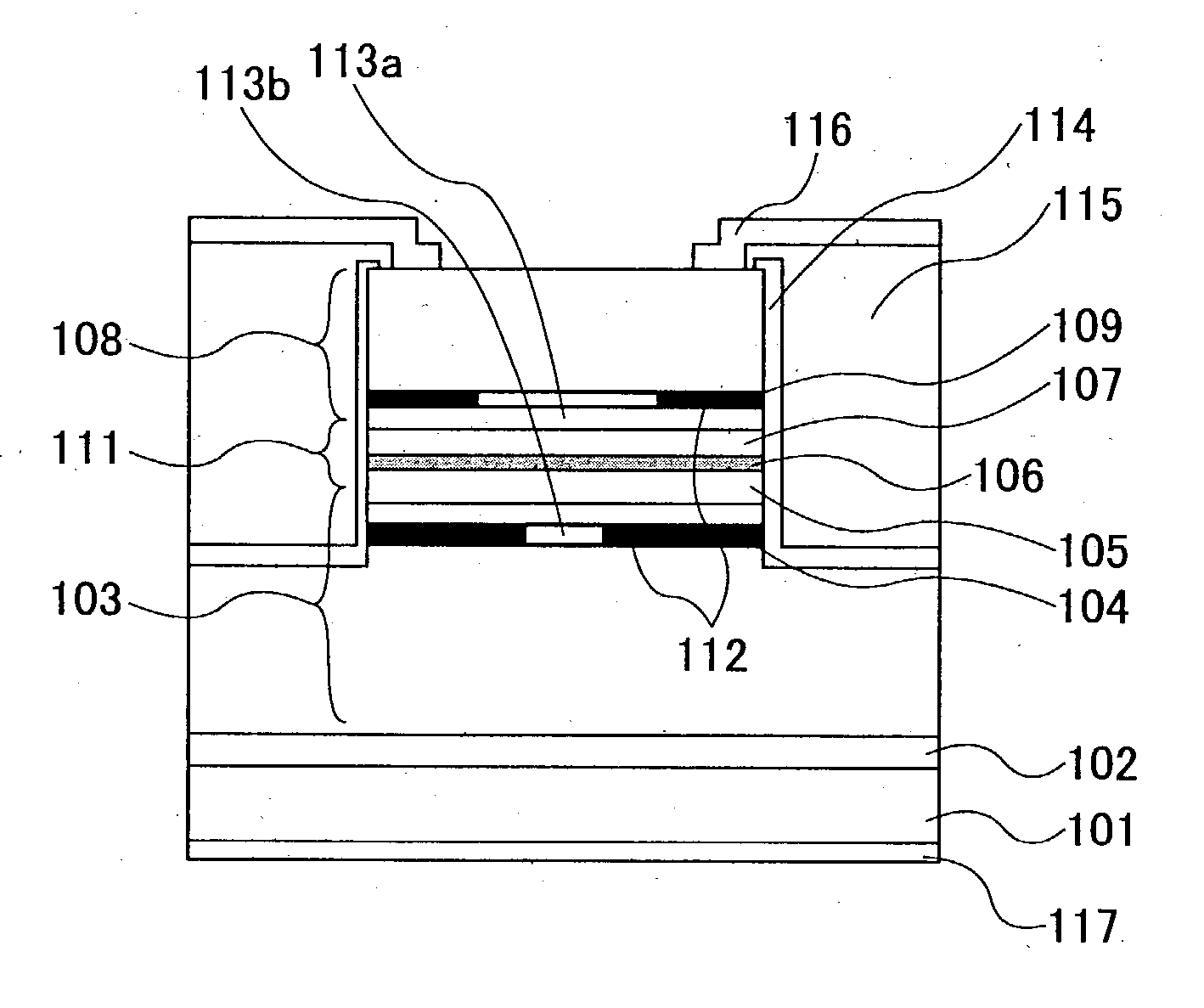
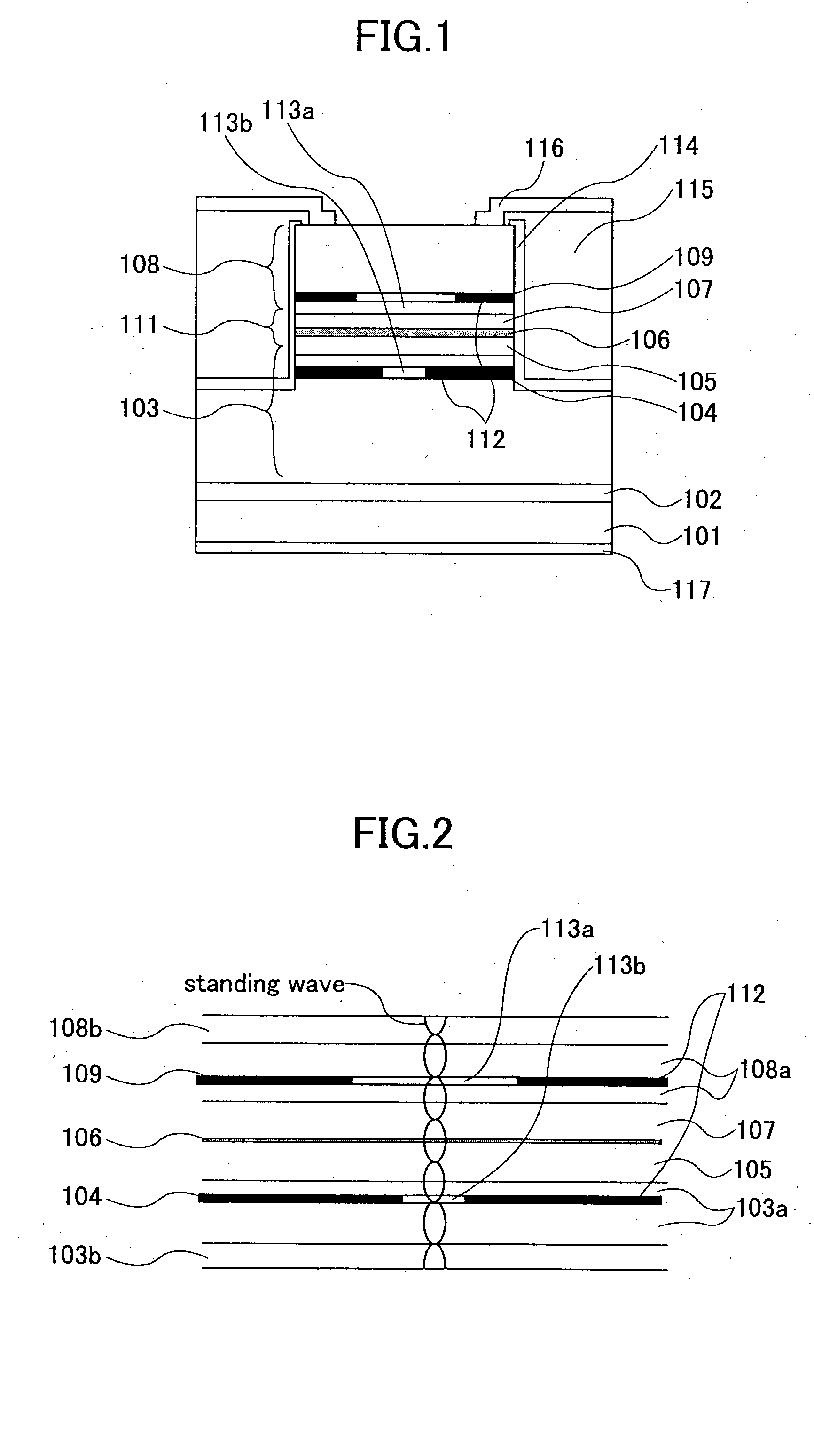
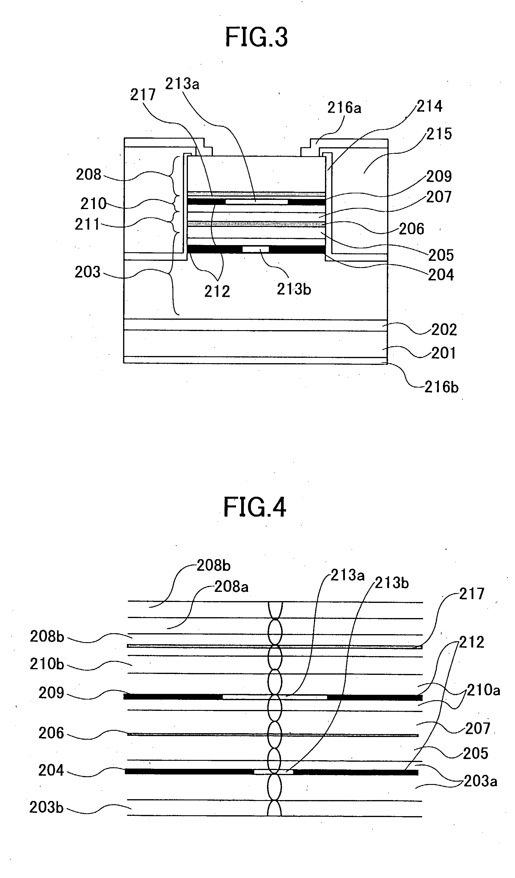
[0029] The selective oxidation structure having the smaller non-oxide region in the electron passage functions as an optical mode control structure to suppress high-order transverse-mode oscillation, while the selective oxidation structure having the larger non-oxide region in the hole passage functions as a hole restricting structure. In this manner, a hole restricting structure and an optical mode control structure are provided separately from each other, and the optical mode control structure that requires a very small non-oxide region is provided in the electron passage (in an n-type semiconductor) that does not increase resistance. Thus, increases of device resistance are prevented.
[0031] Here, the selective oxidation structure including the smaller non-oxide region located outside the carrier passages serves as an optical mode control structure, while the selective oxidation structure having the larger non-oxide region located in the hole passage serves as a hole restricting structure. In this manner, the hole restricting structure and the optical mode control structure are provided separately from each other, and the optical mode control structure requiring a very small non-oxide region is located in a region that does not meet the carrier passages and does not affect the device resistance. Thus, increases of device resistance can be prevented.

Problems solved by technology

However, the amount of confined light increases at the same time.
However, a very small oxidation confinement structure causes various problems, such as an increase of resistance, as will be described later in detail.
As a result, it becomes difficult to achieve high outputs.
In addition to the above problem, the device resistance increases with the decrease of the area of the conductive region, and high-output oscillation becomes difficult due to output saturation caused by device heat generation.
Especially with a p-type semiconductor material, the effective mass of holes is great, and the mobility is low.
However, such a large oxidation confinement structure cannot effectively suppress high-order transverse-mode oscillation, resulting in frequent occurrence of high-order transverse-mode oscillation.
For the above reasons, single fundamental transverse-mode oscillation cannot be achieved with high outputs.
Furthermore, it is difficult to have high outputs, because of the smaller oscillation region and an increase of heat generation due to the higher resistance.
As the device resistance is very high, it is also difficult to perform high-speed modulation.
Further, as the oxidation confinement structure that confines holes occupies most of the area of the p-type distributed Bragg reflector, the device resistance becomes very high, and it is very difficult to perform high-output operations.
Also, as an oxidation confinement structure of a small size is employed as the hole restricting structure, the device resistance is still very high, and it is difficult to have high outputs.

Method used


Image

  • Surface-emitting laser diode having reduced device resistance and capable of performing high output operation, surface-emitting laser diode array, electrophotographic system, surface-emitting laser diode module, optical telecommunication system, optical interconnection system using the surface-emitting laser diode, and method of fabricating the surface-emitting laser diode
  • Surface-emitting laser diode having reduced device resistance and capable of performing high output operation, surface-emitting laser diode array, electrophotographic system, surface-emitting laser diode module, optical telecommunication system, optical interconnection system using the surface-emitting laser diode, and method of fabricating the surface-emitting laser diode
  • Surface-emitting laser diode having reduced device resistance and capable of performing high output operation, surface-emitting laser diode array, electrophotographic system, surface-emitting laser diode module, optical telecommunication system, optical interconnection system using the surface-emitting laser diode, and method of fabricating the surface-emitting laser diode

Examples


eighth embodiment

[0201] An eighth embodiment of the present invention is a surface-emitting laser diode that has the same structure as one of the surface-emitting laser diodes of the first through seventh embodiments, except that at least one of the distributed Bragg reflectors is a n-type semiconductor distributed Bragg reflector, and that a tunnel junction is provided between the n-type semiconductor distributed Bragg reflector and the active layer.

[0202] With this structure of the eighth embodiment that employs an n-type semiconductor distributed Bragg reflector with a small absorption loss, instead of a p-type semiconductor distributed Bragg reflector, a highly efficient surface-emitting laser diode can be obtained.

ninth embodiment

[0203] A ninth embodiment of the present invention is a surface-emitting laser diode that has the same structure as one of the surface-emitting laser diodes of the first through eighth embodiments, except that at least one of the distributed Bragg reflectors is a non-doped semiconductor distributed Bragg reflector or a Bragg reflector partially including a region formed by a non-doped semiconductor distributed Bragg reflector, and that an electrode for confining carriers is provided on a semiconductor layer between the active layer and the non-doped semiconductor distributed Bragg reflector or the region formed by a non-doped semiconductor Bragg reflector.

[0204] With this structure of the ninth embodiment that employs a non-doped semiconductor distributed Bragg reflector with a small absorption loss, a highly efficient surface-emitting laser diode can be obtained.

tenth embodiment

[0205] A tenth embodiment of the present invention is a surface-emitting laser diode having the same structure as one of the surface-emitting laser diodes of the first through ninth embodiments, except that the hole restricting structure in the hole passage is provided at a location corresponding to an antinode of the standing wave of oscillating light.

[0206] With this structure of the tenth embodiment, the optical mode control structure formed by the selective oxidation structure provided at a location corresponding to an antinode of the standing wave of oscillating light can retrain high-order transverse-mode oscillation with greater effect.


PUM


Abstract

A surface-emitting laser diode device that oscillates in a direction perpendicular to the substrate is provided. This surface-emitting laser diode device includes: an active layer; a resonator structure including a first distributed Bragg reflector and a second distributed Bragg reflector that face each other and sandwich the active layer; a hole passage that extends from a first electrode to the active layer; an electron passage that extends from a second electrode to the active layer; a hole restricting structure that is located in the hole passage and defines a region for confining holes to the active layer; and an optical mode control structure that includes a non-oxide region provided in the resonator structure and an oxide region surrounding the non-oxide region, each region containing Al as a constituent element. In this surface-emitting laser diode, the area of the non-oxide region is smaller than the area of the hole restricting structure.

Description

CROSS-REFERENCE TO RELATED APPLICATIONS [0001] The present invention is based on Japanese Laid-Open Patent Application Nos. 2002-46373, 2002-373863, 2002-228702, and 2003-32758, filed on Feb. 22, 2002, Dec. 25, 2002, Aug. 6, 2002, and Feb. 10, 2003, respectively, the entire contents of which are hereby incorporated by reference. BACKGROUND OF THE INVENTION [0002] The present invention relates to a surface-emitting laser diode, a surface-emitting laser diode array, an electrophotographic system, a surface-emitting laser diode module, an optical communication system, an optical interconnection system using the surface-emitting laser diode, and a method of fabricating the surface-emitting laser diode. [0003] A surface-emitting laser (a surface-emitting laser diode) has an active layer that is smaller in volume than that of an edge-emitting laser, and can perform high-speed modulation. For this reason, surface-emitting lasers are attracting more attention as light sources for communicat...

Claims


Application Information

Patent Timeline
IPC IPC(8): H01S5/187H01S3/08H01S5/00H01S5/183H01S5/22H01S5/323H01S5/343H01S5/42
CPCB82Y20/00H01S5/02284H01S5/18313H01S5/1833H01S5/18341H01S5/18358H01S2304/04H01S5/3095H01S5/34306H01S5/3432H01S5/34326H01S5/423H01S2301/166H01S5/18369H01S5/02251
Inventor JIKUTANI, NAOTOSATO, SHUNICHITAKAHASHI, TAKASHI
Owner RICOH KK
Learn More