Eureka AIR delivers breakthrough ideas for toughest innovation challenges, trusted by R&D personnel around the world.

Emergency vehicle traffic signal preemption system

a technology for emergency vehicles and traffic signals, applied in vehicle position/course/altitude control, process and machine control, instruments, etc., can solve the problems of severe operational limitations, severe disruption of the normal phasing pattern of traffic controllers, and present systems used to preempt traffic signals and clear intersections for emergency vehicles responding to life-saving events often come with severe limitations, etc., to achieve the effect of sufficient tim

Inactive Publication Date: 2005-05-19
CALIFORNIA INST OF TECH
View PDF64 Cites 250 Cited by
  • Summary
  • Abstract
  • Description
  • Claims
  • Application Information

AI Technical Summary

Benefits of technology

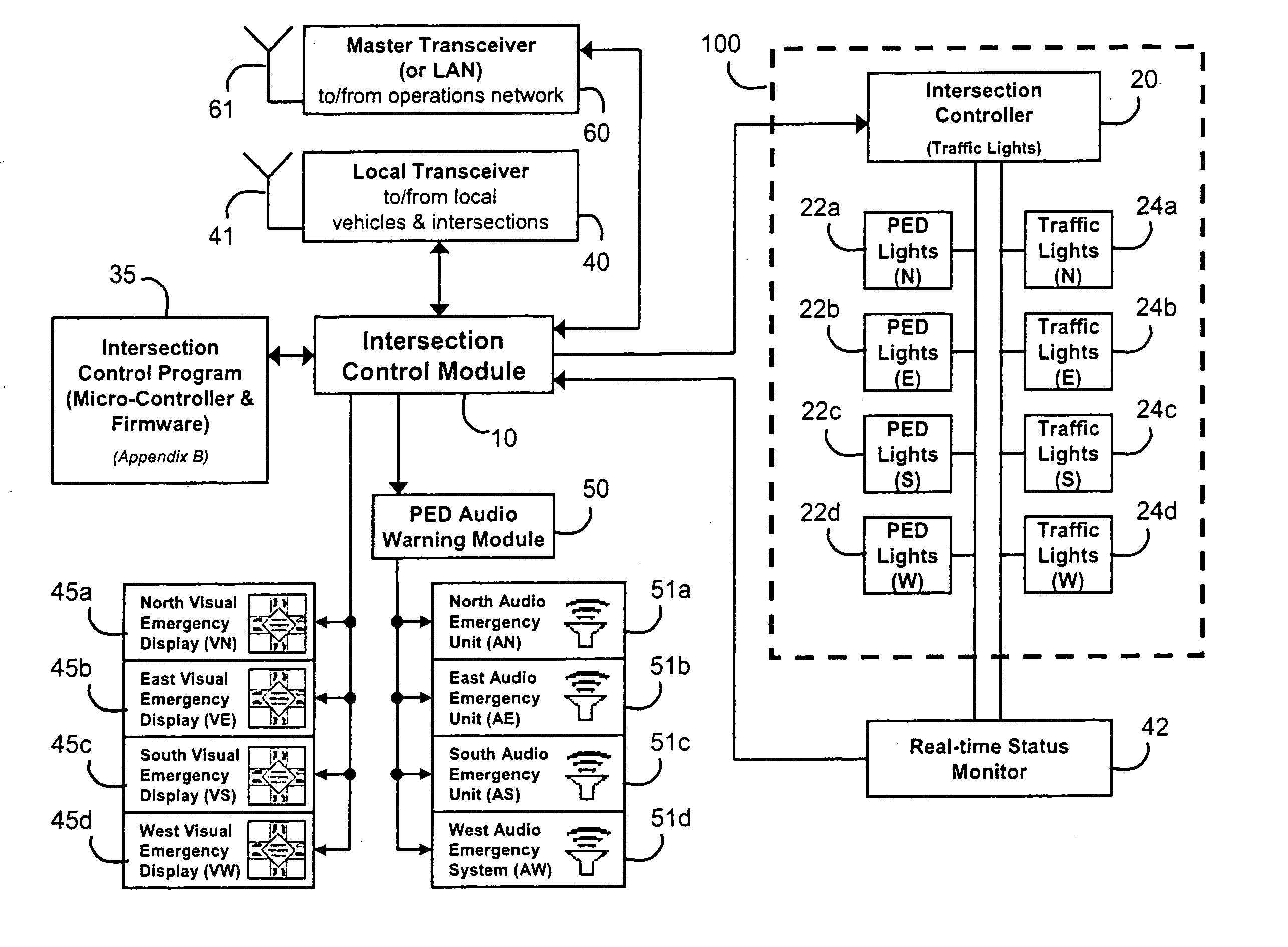
[0017] The purpose of the present invention is to provide an improved emergency vehicle traffic signal preemption system including autonomous operation, real-time phase monitoring and visual / audio signals to alert motorists and pedestrians of the approach of emergency vehicles.
[0024] It also calculates when to trigger the pedestrian-inhibit function to prevent clearance for crossing access. When preemption starts, intersection-based warning displays are sent coded commands via a wireless or hard-line connection to light the proper icons. For each direction, the displays show all preempting emergency vehicles' direction and location, and light the appropriate emergency vehicle message (i.e. “Warning Emergency Vehicle”). All this takes place in real time, in a manner appropriate to insure an intersection is preempted early enough for safe and clear access, and in such a way as to minimized speed reduction for the emergency vehicles.
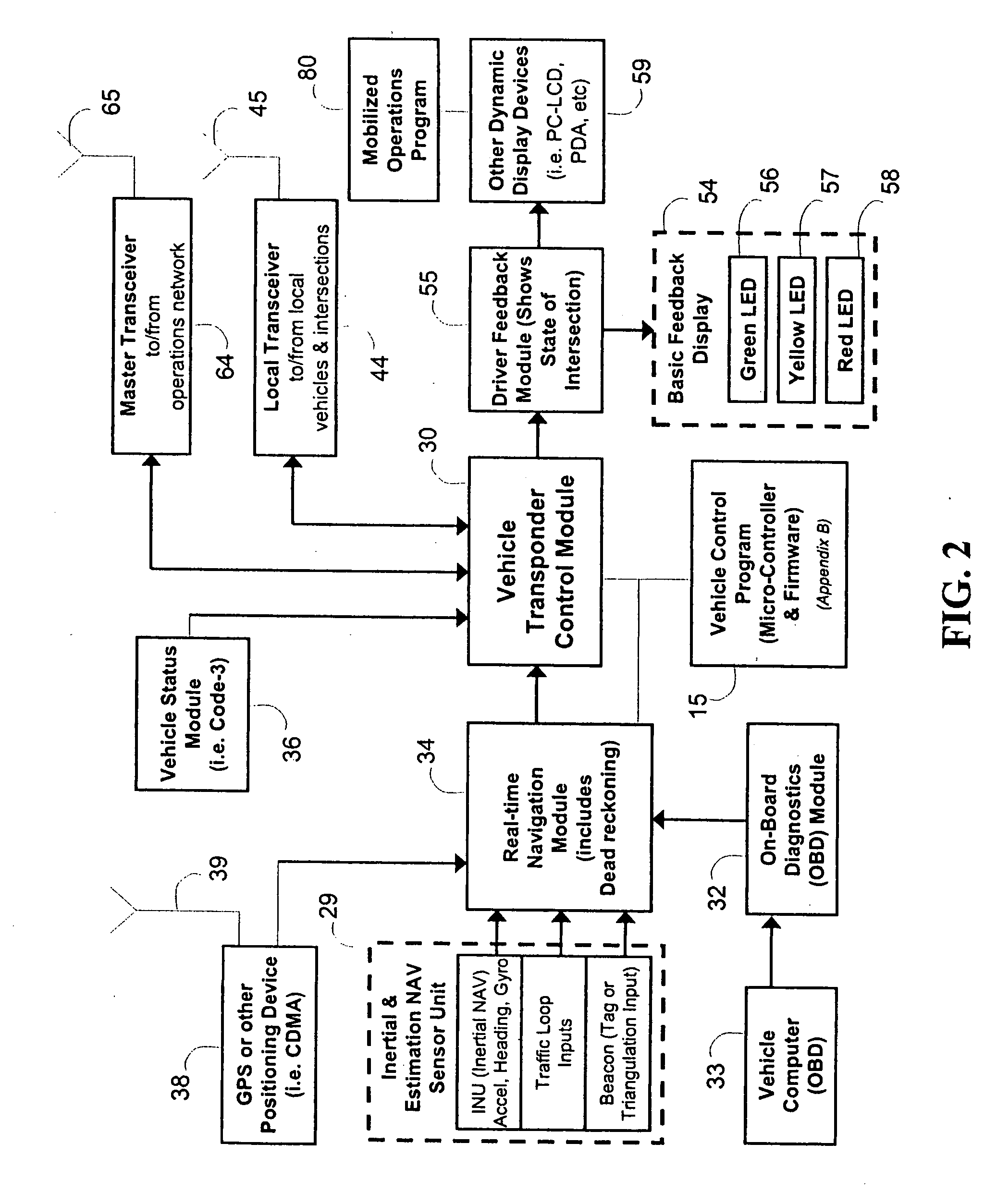
[0025] The system disclosed herein provides a number of improvements of the above-identified patent. It is an autonomous system that does not need involvement of emergency vehicle operator. It also includes expanded system capabilities using emergency vehicle on-board diagnostics (OBD), monitoring multiple emergency vehicles approaching the same intersection using Global Positioning System (GPS), and speed and heading information for multiple emergency vehicles to determine the right of way. An intersection status is transmitted to emergency vehicle dashboards indicating when the intersection is safe to traverse. A dashboard display indicates to the vehicle operator the status of an intersection. The system is also capable of providing dynamic and customized displays via an interface to the vehicle-based PC (personal computer) systems. This interface provides detailed, real-time positioning and status of all neighboring emergency vehicles and intersections. It allows e-operators to view maps with active vehicles and also allows for enhanced conflict detection notification. The system also includes a wide area wireless RF communication links between emergency vehicles and intersections. This system is reliable and unaffected by weather, rain, or lack of line of sight.
[0029] The system transmits a signal causing all traffic lights at an intersection to switch to “red” thus stopping all traffic in all directions. In addition, the display panels flash a relatively large “emergency vehicle” therein with a graphic display indicating the lane and direction of traffic taken by an emergency vehicle. The range of the infrared transmitter can be as much as 1,000 feet allowing sufficient time to clear the intersection. The new improved system utilizes a wide area wireless RF two-way communication link between emergency vehicles and intersections. This method is more reliable and not affected by weather, lack of line of sight, range limitation or obstructions.
[0030] Another advantage of the two-way wireless RF communications link between the intersections and emergency vehicles is the ability to display much more useful data in the vehicles helping the vehicle operator maneuver his vehicle most efficiently and safely. This data includes (but is not limited to) emergency-code levels, vehicle acceleration, vehicle type, and vehicle health. This method also enables feedback communication to be sent from the intersections to the vehicles, providing vehicle-based warnings (or confirmation) of system activity. Intersection “green” status shows when an intersection has been preempted and priority is given to the receiving vehicle, allowing safe passage. If more than one emergency vehicle approaches an intersection, the system determines which vehicle should have the right of way depending on location information (GPS, traffic loop, beacon, etc.), direction and speed sent to the intersection control. A proprietary control program determines the right of way and sends the result to emergency vehicles. The encrypted data package transmitted over transceivers is tagged with the vehicle ID and time to insure proper and certified utilization.
[0032] Another goal of the improved system is creation of an autonomous system that is activated by reception of a priority-code (i.e. Code-3) status or alarm. The operator of the emergency vehicle can concentrate on his primary duty which is to arrive at the sight of the emergency safely in the shortest time possible without worrying about the activation of the system. A priority-code starts the process of communication between an intersection that is being approached and the emergency vehicle and the system performs the functions described above. Also, both vehicle-based warnings and intersection-based warnings provide positive feedback that an e-operator has secured an intersection. This directly translates into a reduction of emergency workers' stress levels.

Problems solved by technology

Present systems used to preempt traffic signals and clear intersections for emergency vehicles responding to a life-saving event often come with severe limitations.
All of these systems have severe operational limitations affected by weather, line of sight, and critical range.
These systems often have further drawbacks requiring them to be activated by the emergency vehicle operator or first responder (herein referred to as “e-operator”).
These systems also severely disrupt the normal phasing patterns of a traffic controller's nominal programming because these systems do not provide real-time monitoring of intersection phases or timing.
Such preemption systems compromise motorist and e-operator safety, as there is no awareness of a traffic-light preemption event (referred herein as “silent preemption”).
Additionally, these systems fail to provide real-time feedback to e-operators through warning devices inside their vehicles (herein referred to as “vehicle-based warnings”).
These factors have the effect that e-operators do not get the feedback required and soon stop using the system.
Visual intersection-based warnings may fail to get the attention of pedestrians standing near an intersection.
There is also the difficulty that pedestrians may often be in harms way if they fail to hear an approaching emergency vehicle.
Although vehicle sirens are especially loud, many circumstances can lead to dangerous situations and potential injury.
Likewise, in extremely busy metropolitan intersections, ambient noise in the building occlusions may prevent warning of the emergency vehicle until just seconds before the vehicle arrived at an intersection.

Method used


Image

  • Emergency vehicle traffic signal preemption system
  • Emergency vehicle traffic signal preemption system
  • Emergency vehicle traffic signal preemption system

Examples


Embodiment Construction

[0052] The three major subsystems in the emergency vehicle traffic signal preemption system are shown in FIG. 5: the vehicle transponder 200, the intersection hardware 230, and the communications and operations network 260.

[0053] The vehicle transponder 200 is composed of three main components. First, the vehicle computer interface module 205 includes the on-board diagnostics circuit and the emergency priority code interface. Second, the navigation predict module 210 uses navigation sensors such as GPS and INU (inertial NAV unit) sensors to generate both absolute and estimated dead reckoning position reports. Third, the transponder control module 215 provides an interface to the e-operator via LEDs, PC display, or PDA device.

[0054] The intersection hardware 230 is composed of three main components. First, the intersection monitor module 235 provides real-time reading and logging of controller signal and pedestrian phasing and timing. Second, the intersection control module 240 per...


PUM


Abstract

An emergency vehicle traffic light preemption system for preemption of traffic lights at an intersection to allow safe passage of emergency vehicles. The system includes a real-time status monitor of an intersection which is relayed to a control module for transmission to emergency vehicles as well as to a central dispatch office. The system also provides for audio warnings at an intersection to protect pedestrians who may not be in a position to see visual warnings or for various reasons cannot hear the approach of emergency vehicles. A transponder mounted on an emergency vehicle provides autonomous control so the vehicle operator can attend to getting to an emergency and not be concerned with the operation of the system. Activation of a priority-code (i.e. Code-3) situation provides communications with each intersection being approached by an emergency vehicle and indicates whether the intersection is preempted or if there is any conflict with other approaching emergency vehicles. On-board diagnostics handle various information including heading, speed, and acceleration sent to a control module which is transmitted to an intersection and which also simultaneously receives information regarding the status of an intersection. Real-time communications and operations software allow central and remote monitoring, logging, and command of intersections and vehicles.

Description

[0001] This application is a Continuation-In-Part of application Ser. No. 10 / 642,435, filed Aug. 15, 2003, and Application Ser. No. 60 / 403,916 filed Aug. 15, 2002. The invention described herein was made in the performance of work under a NASA contract and is subject to the provisions of Public Law 96-517 (U.S.C. 202) in which the Contractor has elected to retain title.BACKGROUND OF THE INVENTION [0002] 1. Field of the Invention [0003] This invention relates to systems for controlling vehicle traffic signals to allow safe passage of emergency vehicles and more particularly relates to a system for autonomously preempting traffic signals at an intersection that includes a vehicle transponder, a real-time intersection controller and monitor (with an intersection-based visual and / or audio alarm warning system), an operations display and control software, and a wide-area communications network. [0004] 2. Background Information [0005] Present systems used to preempt traffic signals and cl...

Claims


Application Information

Patent Timeline
Patent Type & Authority Applications(United States)
IPC IPC(8): G08G1/07G08G1/087G08G1/095
CPCF41G9/00G05D1/02G08G1/00G08G1/095G08G1/07G08G1/087G08G1/01
Inventor BACHELDER, AARON D.FOSTER, CONRAD F.
Owner CALIFORNIA INST OF TECH
Why Eureka
Eureka Blog
Learn More