Ultrasonic imaging with spot focused waves

a technology of spot focused waves and ultrasonic imaging, which is applied in the field of ultrasonic imaging with spot focused waves, can solve the problems of previous imaging technology not adequately meeting the challenge of imaging, poor image quality, and wave propagation perturbation, so as to achieve the effect of restoring the intended signal spectrum, predicting and accurately compensating, and wide bandwidth operation

Inactive Publication Date: 2005-05-19
BULLIS JAMES K
View PDF10 Cites 11 Cited by
  • Summary
  • Abstract
  • Description
  • Claims
  • Application Information

AI Technical Summary

Benefits of technology

[0033] Compensation for frequency dependent attenuation by the medium enables wide bandwidth effects that function as if there was no attenuation by the medium. This compensation is arranged in relation to the focus spot. Attenuation leveling to maintain uniform amplitude wavefronts sets up a condition where all paths undergo a known attenuation process. The pre-set depth defines approximate propagation path lengths. Therefore, it is possible to predict and accurately compensate for that frequency dependent attenuation, and thus restore an intended signal spectrum. It is then possible to fully realize the benefits of wide bandwidth operation. Effectiveness of this compensation requires that the depth of field causes a spot that is small enough that compensation can be reasonably effective for a path to any point in the spot.
[0034] The selective sensing spot serves to suppress signals that arise from effects outside the spot. Such sensing is most effective when both transmit and receive operations cause focusing effects that overlay to mutually reinforce the focusing effects.
[0035] Spot focusing benefits accrue at the expense of image acquisition time, as compared with that of conventional medical ultrasound devices. A rapid scanning operation partially makes up for this penalty, where transmit-receive events are in a rapid sequence, where the transmit-receive events overlap in time. Mutual interference due to cross-over effects is suppressed by a coding method, where correlation processing is made simple by the pre-set depth that for each transmit-receive operation. A correlator channel produces a single image data sample for each spot. The compensation apparatus is combined with the coding apparatus, where coded signal waveforms are modified by compensating adjustments. Such adjustments can be applied at various points in the system, where one set of adjustments applies for a focus spot. The adequacy of a single set of adjustments also helps simplify the equipment.
[0036] Cross-over interference is further suppressed where a bistatic arrangement is used. An additional advantage of the bistatic arrangement is that switching from transmit to receive is not required and transmit events can be done at the same time that receive events occur. This enables even more overlap of transmit-receive events with reduced concern for linearity problems.

Problems solved by technology

While available ultrasound apparatus fills these requirements, image quality is poor due to difficulties that arise with examination of living soft tissue that exists as a volume.
Additionally, in the tissue that contains variations that are being sensed, the same variations cause perturbations of wave propagation.
Previous imaging technology has not adequately met the challenge of imaging in this volumetric distribution of tissue variations.
The Rayleigh Criterion provides fundamental performance limits of many types of devices, where such limits are a result of focusing effects.
An obvious adaptation of this microscopic form of device to imaging in living tissue volumes using the demonstrated mechanical scanning methods would entail an examination time that would be unsuitable for examination of a living patient.
Unfortunately, picture quality did not approach that of the microscope form device, probably due to uneven attenuation effects.
While this architectural adaptation has resulted in useful ultrasound equipment, human tissue often presents difficulties that cause unsatisfactory results.
Adapting basic radar architecture to medical ultrasound applications is particularly problematic because of the volumetric distribution of objects.
Consequently, The elevation beamwidth is a significant problem.
Since vertically distributed objects are at the same range, range resolution does not provide a capability to distinguish among them.
This failure to resolve means that small detail of disease processes is not discernable.
It also means that disease processes that produce weak reflection signals can not be seen because the wide beam does not enable exclusive sensing such that weak signals are buried in a summed signal, where the summed signal includes all tissue effects in the beam as a single image sample.
In a time based system architecture, such as typical ultrasound architecture, it is not possible to provide adequate control of this elevation beamwidth because there is conflict between focusing resolution and the range extent over which range can be scanned using the time base.
When depth of field becomes very small, the result of a given transmit-receive event is a focused range extent that is very short, and the fired line is so short that a useful image can not be formed.
Transmit focus is more difficult, since a given transmission must be focused in advance.
It did not provide a method of simultaneous transmission of waves in different directions.
In typical time based scanning apparatus, such replica correlation becomes complicated, since it must perform a time compression process.
However, the possible transducer area was partially utilized to enable rapid acquisition, such that focusing capability was not fully realized.
However, as with the two preceding references, azimuth and elevation focusing was accomplished jointly through the transmit transducer array and the receive transducer array, and focusing power was not maximized.
A review of the past research record suggests that attenuation effects are a significant cause of focus degradation in breast tissue, especially for cases of women at the ages of greater vulnerability to breast cancer where breast tissue tends to contain a greater percentage of fat.
A further difficulty with adapting simple radar architecture to medical ultrasound applications is that air is the medium of propagation for radar signals whereas irregular human tissue is the medium of propagation of medical ultrasound signals.
The radar wave signals are only slightly distorted by the air, but the medical ultrasound wave signals are significantly distorted by the tissue effects.
The radar architecture, when adapted to medical ultrasound use, does not allow adequate aperture area to contend with propagation distortion effects that degrade resolution, where this causes further deterioration in disease sensing capability.
This fails to correctly understand distortion effects.

Method used


Image

  • Ultrasonic imaging with spot focused waves
  • Ultrasonic imaging with spot focused waves
  • Ultrasonic imaging with spot focused waves

Examples


Embodiment Construction

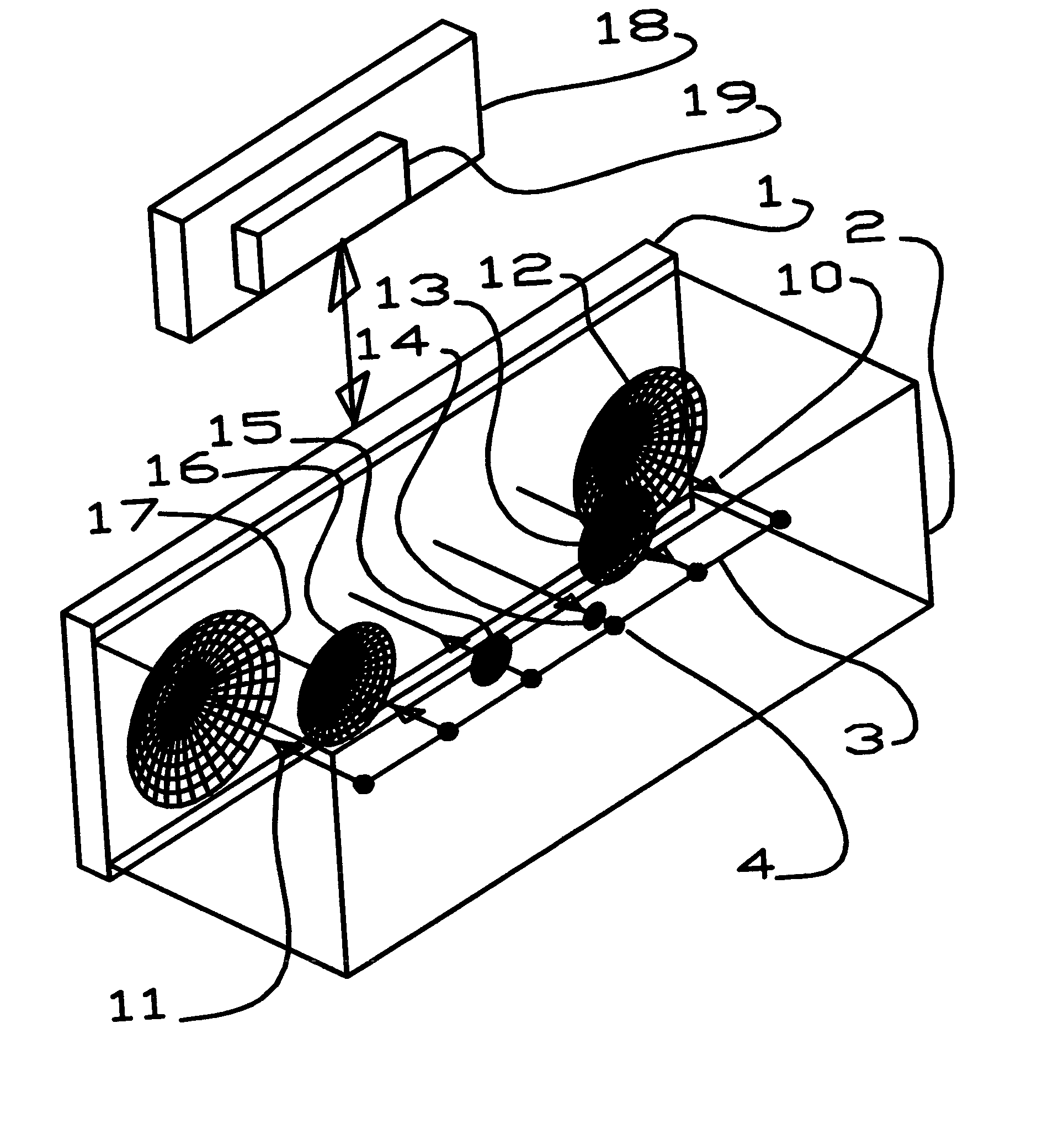
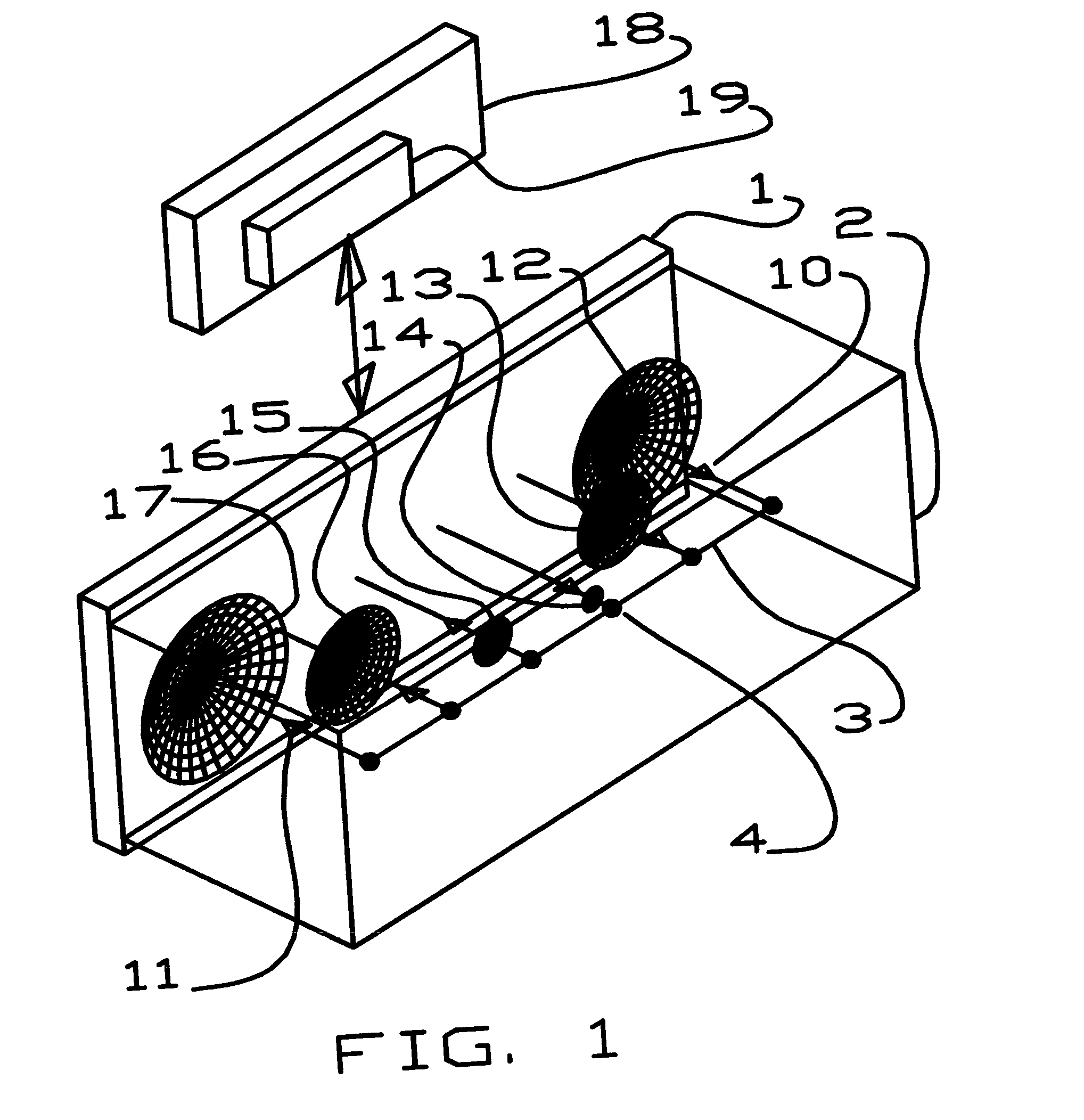
[0053] The invention is designed to provide high resolution medical imaging that is incomparably superior to that achieved by conventional ultrasound technology. Furthermore, problems of conventional ultrasound technology relative to operation in real tissue must be solved.

[0054] The key objective is to resolve all possible dimensions of information to the greatest possible degree, especially where coherent conditions support such resolution. A common improvement opportunity in a variety of sensor technologies is left open by incomplete utilization of possible aperture space in conventional architecture. The medical need for much better imaging motivated exploration of such opportunities. Even though there have been significant complications, a revolutionary new architecture has been developed to enable sensing of early disease processes in soft tissue. The new architecture utilizes very large, two dimensional apertures for both transmit and receive operations. This gives the best ...


PUM


Abstract

The invention is a system that was developed for medical imaging, with particular attention to breast imaging applications. Spot focused architecture enables very high resolution imaging using very large aperture transducer arrays, where depth of field and focal length cause a small focused spot at a pre-set depth for each transmit-receive operation. Scanning depends on rapid movement of the focus spot throughout an intended object space, so transmit-receive events are overlapped in time. Coded signals are used to suppress interference caused by such overlap. Selection of codes by pre-set correlation is simple, where a correlator channel produces a single image data sample for each spot. Coded signals are compensated for frequency dependent attenuation by the medium to enable wide bandwidth effects. Attenuation leveling and fixed paths to spots enable prediction and compensation for frequency dependent attenuation to enable broad band effects. The architecture provides for bistatic operation of sparse arrays, with hybrid electronic beamformers. It also uses mechanical scanning. Transducer elements are constructed by cutting strips from thin cards of piezo-electric material.

Description

[0001] This patent document contains material that is subject to copyright protection. Facsimile reproduction is allowed of the patent document or the patent disclosure as is appears in the Patent and Trademark Office patent file or records as allowed by US patent law, but otherwise all copright rights are reserved. CROSS REFERENCE TO RELATED APPLICATIONS [0002] Application Ser. No. 09 / 975,033 Bullis, filed Oct. 10, 2001, Enhanced Focusing of Propagating Waves By Compensation for Medium Attenuation; application Ser. No. 10 / 060,591, filed Jan. 30, 2002 Bullis, Channeled Wavefield Transformer BACKGROUND OF THE INVENTION [0003] This invention relates to sensing using propagating wave signals. The field of the invention involves propagating waves and transducer operation relative to such waves. The primary area of interest is transmitting waves and receiving waves that arise as a result of objects in a field of view that is a three dimensional volume. Example applications in the field o...

Claims


Application Information

Patent Timeline
Patent Type & Authority Applications(United States)
IPC IPC(8): A61B8/08
CPCA61B8/0825
Inventor BULLIS, JAMES K.
Owner BULLIS JAMES K
Why Eureka
Try Eureka