Gas concentration

a technology of gas concentration and concentration chamber, applied in the field of gas analysis, can solve the problems of limiting the concentration that can occur, the concentrating power cannot be arbitrarily high, and the membrane response time of some species is rather slow, so as to reduce the pressure in the trap

Inactive Publication Date: 2005-05-26
KORE TECH +1
View PDF2 Cites 13 Cited by
  • Summary
  • Abstract
  • Description
  • Claims
  • Application Information

AI Technical Summary

Benefits of technology

[0027] The method may further comprise the step of passing the carrier gas and the analyte through the trap and, more preferably, the pressure of the carrier gas and analyte is at a third pressure which is greater than the first pressure.
[0028] The carrier gas and analyte may be passed through a selectively permeable membrane prior to passing them into the trap. Alternatively or additionally, the analyte may be passed through a

Problems solved by technology

However, it should be noted that, at very high volume ratios, there are problems with the trap material retaining all of the benzene from the sampled air.
Thus, there are limits to the concentration that can occur and so the concentrating power cannot be arbitrarily high.
However, the membrane response time can be rather slow for some species, although the trap can potentially provide a better concentration ratio and also has the possibility of using a temperature programmed desorption to give additional sample information.
This means that the miniature intermediate vacuum pump, which is mechanical and therefore subject to wear, only needs to operate during a measurement.
This greatly simplifies management of the vacuum for the user as well as saving cost, but the implication is that the inner membrane cannot be changed in normal use.
There are not many membrane materials that work well over a wide range of analytes.
The one that most

Method used


Image

  • Gas concentration
  • Gas concentration
  • Gas concentration

Examples


Embodiment Construction

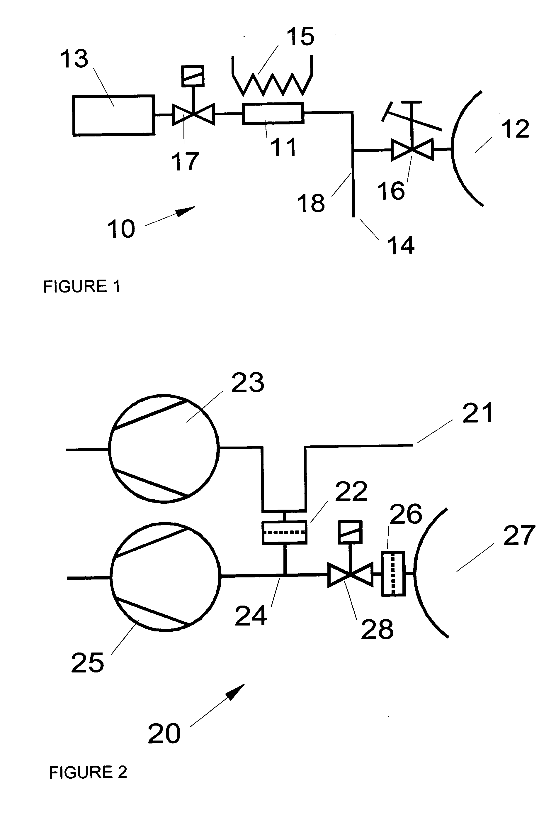
[0051]FIG. 1 shows a simple prior art system 10 to transfer sample from a trap 11 in which the sample has already been retained into a mass spectrometer 12. The system is also provided with a gas supply 13, an exhaust 14, a heater 15 and valves 16, 17. Valve 16 is a leak valve that admits a small portion of the flow into the mass spectrometer (limited by the capacity of the high vacuum pumps required for the mass spectrometer). Heater 15 heats the trap 11 to release the analyte from the absorbent within the trap, valve 17 is opened to allow transport gas from the gas supply 13 to be admitted to the trap 11. This pushes the analyte out of the trap 11, as a relatively concentrated “plug” of gas, and transports it to the mass spectrometer inlet valve 16. Region 18 is normally at, or a little above, atmospheric pressure during this process. Fine control of the timing of opening of valve V2 allows the sample plug to be stopped at the inlet valve 16, if time is needed for the analysis. Th...


PUM


Abstract

A method of concentrating a gaseous substance includes the steps of isolating a trap in which an analyte to be concentrated has been absorbed from a carrier gas passed through the trap and reducing the pressure within the trap to a first pressure. The analyte is desorbed from the trap and the analyte released from the trap is diffused into an analyser operating at a second pressure lower than the first pressure.

Description

BACKGROUND OF THE INVENTION [0001] 1. Field of the Invention [0002] The invention is primarily concerned with gas analysis, where low levels of compounds of interest are to be found in a matrix gas, usually air. [0003] It is particularly relevant to the situation where the analyser is operated in at least a partial vacuum and the gas to be analysed is typically at atmospheric pressure. The exact pressures are not important, except that the invention relies upon a significant pressure difference between the analyser pressure and the pressure of the gas to be analysed. Typically, the analyser is a mass spectrometer which operates at pressures between 10−4 and 10−9 mbar. [0004] It is often the case that the amount of gas that can be admitted to the analyser is limited by the matrix gas, but at the same time the more compound of interest that can be admitted, the greater the sensitivity of the measurement. In these cases, a device that increases the concentration of the compounds of int...

Claims


Application Information

Patent Timeline
IPC IPC(8): G01N27/62G01N1/00G01N1/22G01N1/36G01N1/40G01N33/00
CPCG01N2033/0019G01N1/40
Inventor MULLOCK, STEPHEN JAMESMATSUMOTO, KOICHI
Owner KORE TECH
Why Eureka
Try Eureka