Determinant wing assembly

a wing assembly and determinant technology, applied in the field of determinant wing assembly, can solve the problems of significant growth from the original design dimension, tool that was originally built within tolerance can be distorted out of tolerance from the hard use it typically receives in the factory, and parts that lack the strength and fatigue durability of round holes drilled normal to the part surfa

Inactive Publication Date: 2005-06-02
THE BOEING CO
View PDF8 Cites 96 Cited by
  • Summary
  • Abstract
  • Description
  • Claims
  • Application Information

AI Technical Summary

Benefits of technology

[0009] Accordingly, it is an object of this invention to provide a method of manufacturing large and heavy assemblies, such as airplane wings, from flexible and semi-flexible parts and subassemblie...

Problems solved by technology

Assembly tooling is intended to accurately reflect the original engineering design of the product, but there are many steps between the original design of the product and the final manufacture of the tool, so it is not unusual that the tool as finally manufactured produces missized wings or wing components that would be outside of the dimensional tolerances of the original wing or wing component design unless extensive, time consuming and costly hand work is applied to correct the tooling-induced errors.
More seriously, a tool that was originally built within tolerance can distort out of tolerance from the hard use it typically receives in the factory.
Parts can shift out of their intended position when they are fastened in non-round holes, and the nonuniform hole-to-fastener interference in a non-round hole or a hole that is axially skewed from the hole in the mating part lacks the strength and fatigue durability of round holes drilled normal to the part surface.
The tolerance buildup on the wing subassemblies can result in significant growth from the original design dimensions, particularly when the part is located on the tool at one end of the part, forcing all of the part variation in one direction instead of centering it over the true intended position.
Interference fasteners, such as rivets and lock bolts, and cold working of a fastener hole, both create a pattern of stress in the metal around ...

Method used


Image

  • Determinant wing assembly
  • Determinant wing assembly
  • Determinant wing assembly

Examples


Embodiment Construction

[0039] The invention is described as applied to a preferred embodiment, namely, a process of assembling airplane wings. However, it is contemplated that this invention has general application to the assembly of parts into major assemblies where adherence to a specified set of dimensional tolerances is desired, particularly—where some or all of the parts and subassemblies are flexible or semi-flexible.

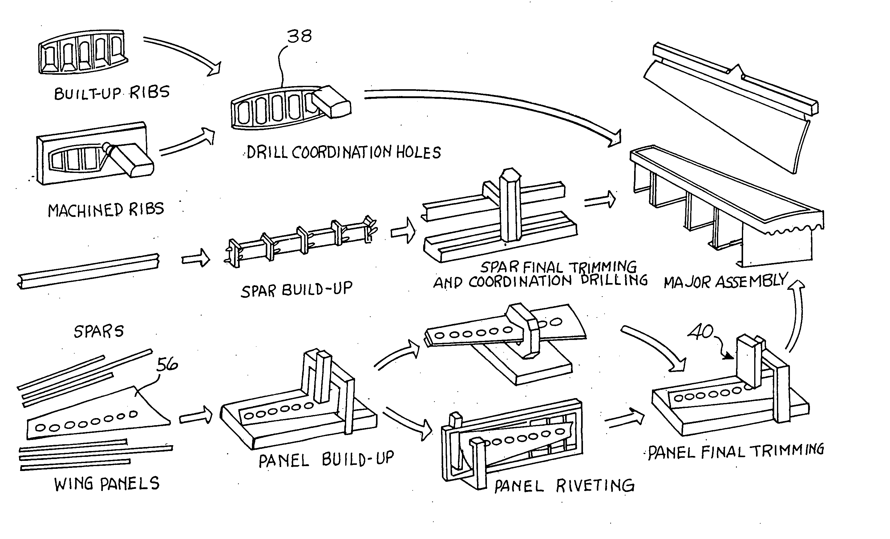
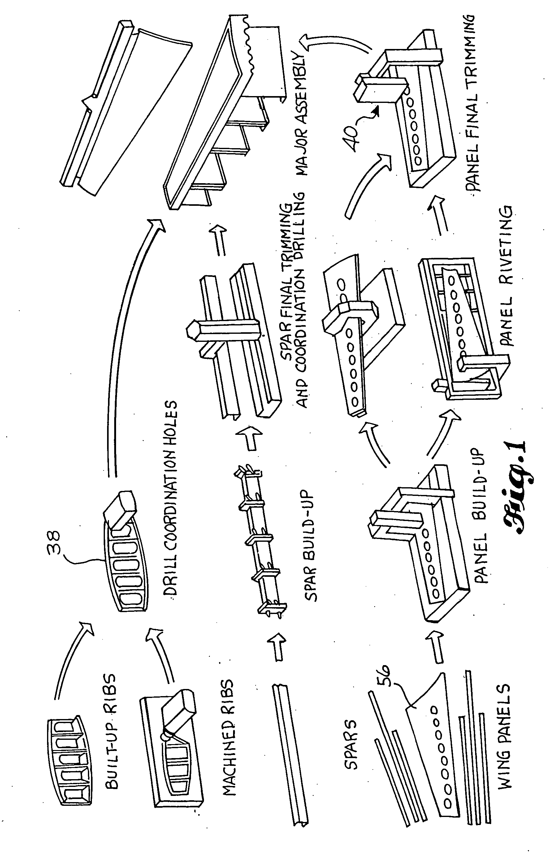
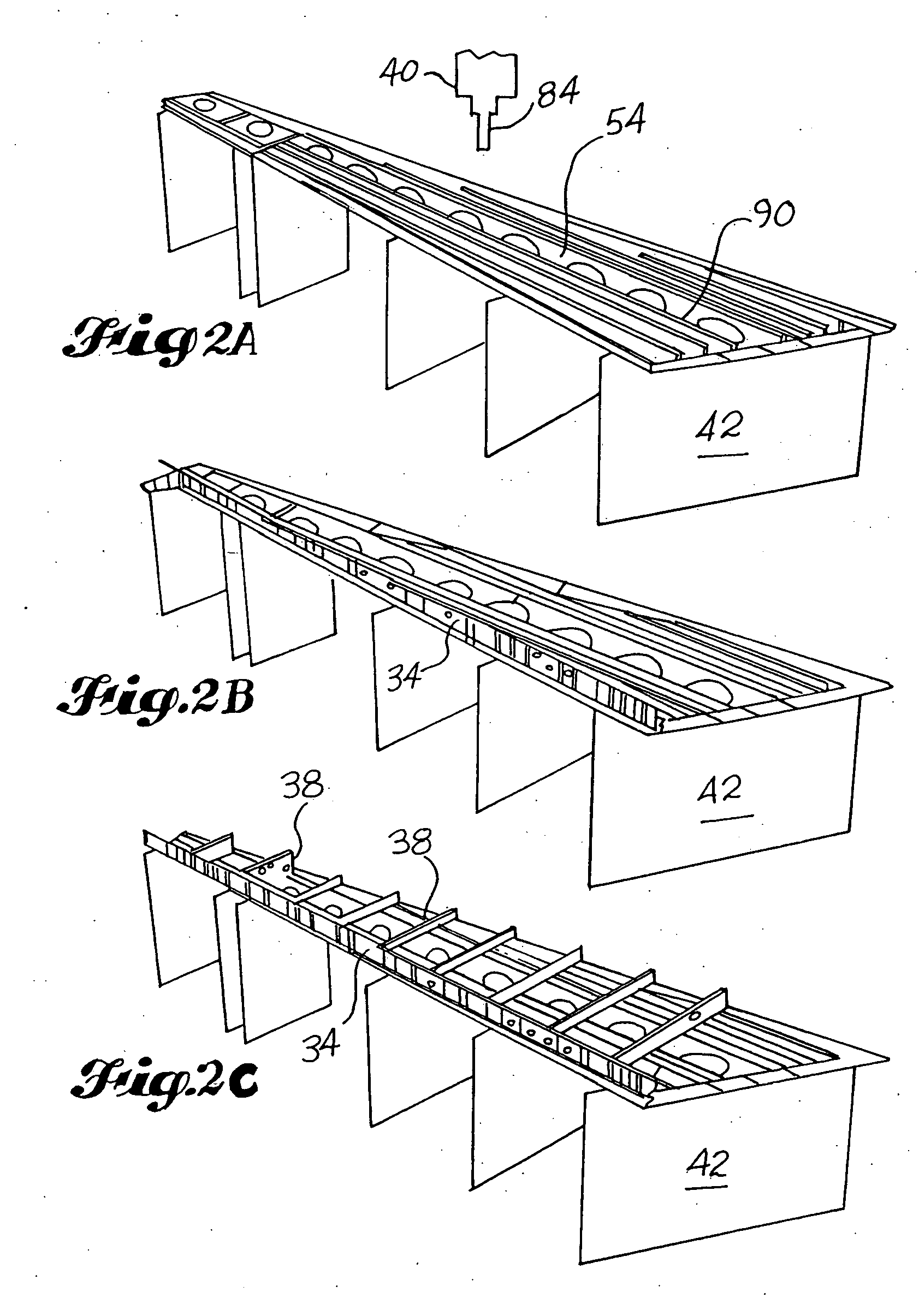
[0040] Referring now to the drawings, wherein like reference characters designate identical or corresponding parts, and more particularly to FIG. 1 thereof, top level schematic diagram illustrates the major process steps in the determinant wing assembly process according to this invention. The process begins with building the major components of the wing, including upper and lower wing panels 30 and 32, a rear spar 34 and a front spar 36, and in-spar ribs 38. The major components are brought together on a computer numerically controlled machine tool 40 and assembled as a wing in the ho...


PUM

PropertyMeasurementUnit
Dimensionaaaaaaaaaa

Abstract

A method and apparatus for manufacturing wings includes a fixture that holds wing panels for drilling and edge trimming by accurate numerically controlled machine tools using original numerical part definition records, utilizing spatial relationships between key features of detail parts or subassemblies as represented by coordination features machined into the parts and subassemblies, thereby making the parts and subassemblies intrinsically determinant of the dimensions and contour of the wing. Spars are attached to the wing panel using the coordination holes to locate the spars accurately on the panel in accordance with the original engineering design, and in-spar ribs are attached to rib posts on the spar using accurately drilled coordination holes in the ends of the rib and in the rib post. The wing contour is determined by the configuration of the spars and ribs rather than by any conventional hard tooling which determines the wing contour in conventional processes.

Description

REFERENCE TO RELATED APPLICATIONS [0001] This application relates to a U.S. Provisional Application No. 60 / 013,986 filed on Mar. 22, 1996, and further to PCT / US97 / 04550 filed Mar. 21, 1997, both entitled “Determinant Wing Assembly” by David Strand, Clayton Munk and Paul Nelson;TECHNICAL FIELD [0002] This invention relates to a method and apparatus for inexpensively manufacturing major airplane assemblies to close tolerances, and more particularly, to a method and apparatus for assembling wing skins, spars, ribs and other components with unprecedented precision to produce a wing having close conformance to the original engineering configuration, while significantly reducing tooling expense. BACKGROUND OF THE INVENTION [0003] Conventional manufacturing techniques for assembling components and subassemblies to produce airplane wings to a specified contour rely on fixtured “hardpoint” tooling techniques utilizing floor assembly jigs and templates to locate and temporarily fasten detaile...

Claims


Application Information

Patent Timeline
IPC IPC(8): B64F5/00
CPCB64F5/0009Y10T29/49895Y10T29/49778Y10T29/53983Y10T29/49998Y10T29/4978Y10T29/49622B64F5/10
Inventor MUNK, CLAYTON L.NELSON, PAUL E.STRAND, DAVID E.
Owner THE BOEING CO
Why Eureka
Try Eureka