Cavity ring-down detection of surface plasmon resonance in an optical fiber resonator

a surface plasmon resonance and cavity detection technology, applied in the direction of optical radiation measurement, photometry using electric radiation detectors, instruments, etc., can solve the problems of difficult use, impractical industrial applications, limited spectroscopic region of crds,

Inactive Publication Date: 2005-06-02
THE TRUSTEES FOR PRINCETON UNIV
View PDF34 Cites 40 Cited by
  • Summary
  • Abstract
  • Description
  • Claims
  • Application Information

AI Technical Summary

Benefits of technology

[0026] A further exemplary embodiment of the present invention is an improved method of detecting environmental changes in a fluid using a surface plasmon cavity ring-down detection (SPCRD) system that includes a surface plasmon resonance (SPR) sensor optically coupled within an optical cavity. The SPR sensor is formed of a metal-coated tapered optical fiber section. Coherent optical radiation, including a predetermined wavelength, is coupled into the optical cavity of the SPCRD system. The power level of

Problems solved by technology

For example, gases such as N2, O2, H2, Ar, and He are used to manufacture integrated circuits, for example, and the presence in those gases of impurities—even at parts per billion (ppb) levels—may prove damaging and reduce the yield of operational circuits.
Unfortunately, these methods have several features, discussed in U.S. Pat. No. 5,528,040 issued to Lehmann, that have made them difficult to use and impractical for industrial applications.
At present, CRDS is limited to spectroscopic regions where high reflectivity dielectric mirrors are produced.
This has significantly limited the usefulness of the method

Method used


Image

  • Cavity ring-down detection of surface plasmon resonance in an optical fiber resonator
  • Cavity ring-down detection of surface plasmon resonance in an optical fiber resonator
  • Cavity ring-down detection of surface plasmon resonance in an optical fiber resonator

Examples


Embodiment Construction

[0044] The entire disclosure of U.S. patent application Ser. Nos. 10 / 644,137 filed on Aug. 20, 2003; Ser. No. 10 / 157,400 filed on May 29, 2002; and Ser. No. 10 / 017,367 filed Dec. 12, 2001 are expressly incorporated herein by reference.

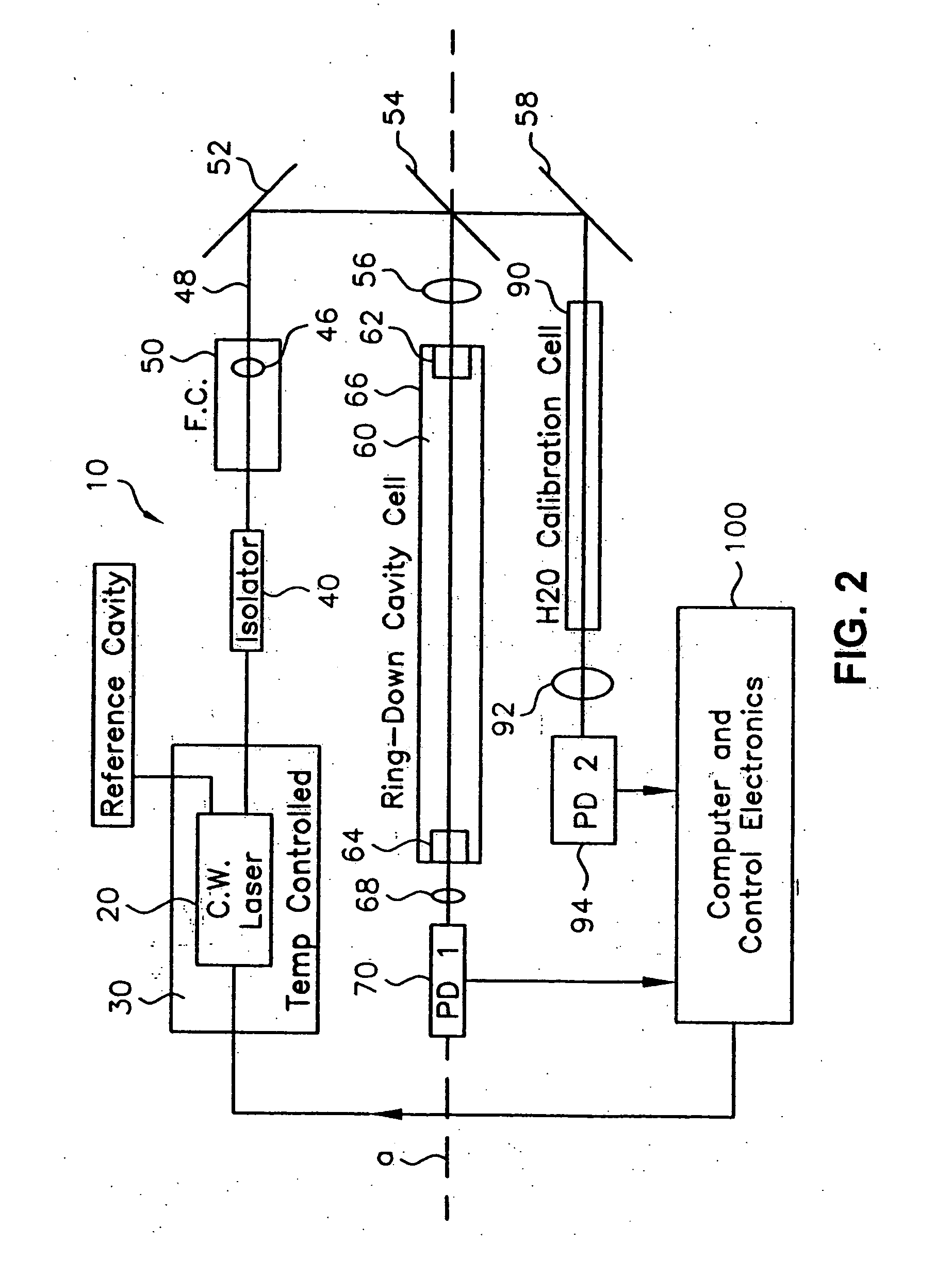
[0045] As described above, CRDS provides a highly sensitive means of measuring analytes in a medium within an optical cavity. Further, Applicants have described in 10 / 157,400 filed on May 29, 2002 and 10 / 017,367 filed Dec. 12, 2001 methods of using the evanescent fields surrounding optical fibers to provide loss in exemplary optical fiber-based ring-down cavities. The present invention extends these methods through the use of surface plasmon resonance (SPR) techniques to improve sensor sensitivity and to expand the types of environmental changes that may be sensed with exemplary sensors according to the present invention.

[0046] SPR spectroscopy is used to measure small changes in refractive index on an external surface of a total internal reflection ...


PUM


Abstract

An apparatus and method for use with a coherent optical source to detect environmental changes. The apparatus comprises: an optical cavity, including an input coupling port, and an optical fiber section; a detector optically coupled to the optical cavity to monitor radiation in the optical cavity; and a processor electrically coupled to the detector for analyzing the environmental changes adjacent the detection portion of the optical cavity based on a rate of decay of the radiation in the optical cavity monitored by the detector. The optical fiber section of the optical cavity includes a detection portion coated with a conductive layer capable of supporting a surface plasmon to provide cavity loss. The surface plasmon is responsive to the environmental changes adjacent the detection portion. The coherent optical source is optically coupled to the input coupling port of the optical cavity to provide the radiation in the optical cavity.

Description

[0001] This application is a continuation-in-part of pending application Ser. No. 10 / 644,137 filed on Aug. 20, 2003, which is a continuation-in-part of pending application Ser. No. 10 / 157,400 filed on May 29, 2002, which is a Continuation-in-Part of pending application Ser. No. 10 / 017,367 filed on Dec. 12, 2001.FIELD OF THE INVENTION [0002] The present invention relates generally to cavity ring-down detection systems which include surface plasmon sensors and, in particular, is directed to measurement of environmental changes in the vicinity of the surface plasmon sensors using cavity ring-down spectroscopy. In particular the present invention may allow for highly sensitive detection of binding events at a coated fiber surface of the surface plasmon detectors. BACKGROUND OF THE INVENTION [0003] Although this application relates to measurement of environmental changes using cavity ring-down assisted surface plasmon detection, the following background in absorption spectroscopy may be ...

Claims


Application Information

Patent Timeline
IPC IPC(8): G01N21/00G01N21/39G01N21/55G01N21/77
CPCG01N21/39G01N21/552G01N21/7746G01N21/554G01N21/553G01N21/17G01N21/55
Inventor TARSA, PETER B.
Owner THE TRUSTEES FOR PRINCETON UNIV
Why Eureka
Try Eureka