Carrier fiber assembly for tissue structures

a tissue structure and carrier fiber technology, applied in the field of carrier fibers, can solve the problems of limited success in the use of autologous cultured cells grown on scaffolds, and achieve the effects of facilitating the assembly of two and three dimensional structures, facilitating the assembly process, and facilitating the rapid assembly of two

Inactive Publication Date: 2005-06-02
WARWICK MILLS INC
View PDF10 Cites 14 Cited by
  • Summary
  • Abstract
  • Description
  • Claims
  • Application Information

AI Technical Summary

Benefits of technology

[0005] In this invention, carrier fiber is used to facilitate the assembly of two and three dimensional structures with autologous tissue. Autologous tissue is harvested from the donor and assembled into complex forms rapidly. The tissue is kept live and viable during extracorporeal assembly and is replaced in the donors body. The use of carrier fiber facilitates this rapid assembly of the two and three dimensional structures. The autologous tissue is modified into thin long sections and is integrated with the carrier fiber. Carrier fiber of various types are used to facilitate the assembly process. The use of twisting, spinning, weaving, knitting, and braiding assembly processes to integrate the carrier fiber and the autologous tissue strips is made practical for assembly into structures by using long pre-threaded carrier yarn leaders for machine set up, in order to draw the autologous tissue into the assembly process when ready. In this way, the limited quantity of autologous tissue is not wasted in the set up and thread-up of the assembly equipment. The finished autologous structures allow for complete healing in the patients body. The carrier fiber of the tissue / fiber composite structure is either bio-absorbed or forms a bio-compatible substructure for the patient's native tissue as healing progresses.

Problems solved by technology

The use of autologous cultured cells grown on scaffolds has been attempted with very limited success.

Method used


Image

  • Carrier fiber assembly for tissue structures
  • Carrier fiber assembly for tissue structures
  • Carrier fiber assembly for tissue structures

Examples


example # 1

EXAMPLE #1

Weaving of Tubular ATY / CF Structures Oriented in the Fill Direction

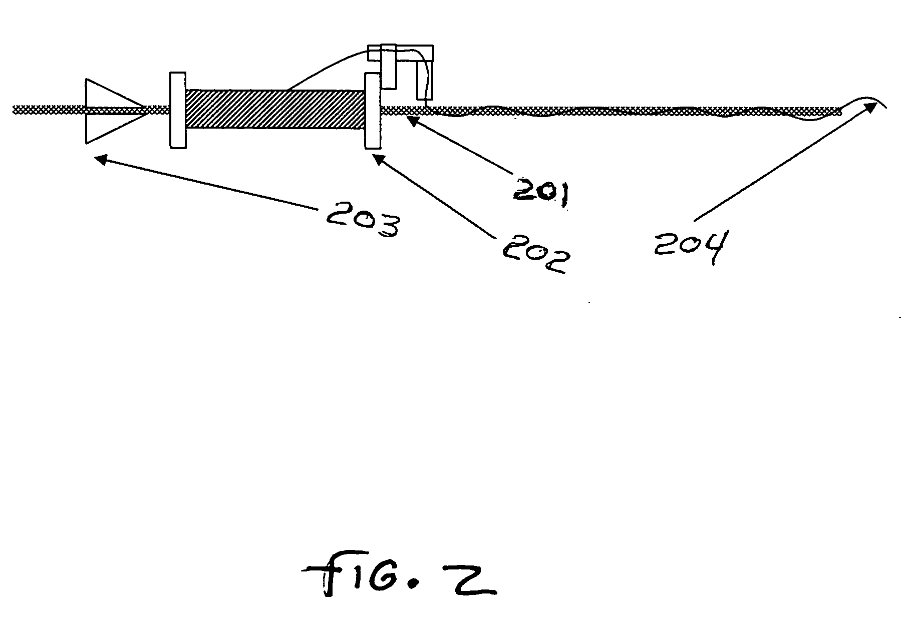
[0026] The first example of an ATY / CF scaffold or structure and process of the invention is of weaving ATY / CF fabric tubes oriented in the fill direction. For this example, cylindrical tubes are fabricated to various lengths and diameters. The use of a weaving process is preferred because it allows separate selection of the thread line density and type in the axial and circumferential directions. Narrow width weaving equipment of a few inches is preferred. Needle or rapier insertion are best for the filling insertion mechanism. Referring to FIG. 4, the major modification of the heddle / reed insertion section 400 is the use of an aqueous saline bath 404 to preserve the viability of live tissue. Tissue yarn ATY 401 is used in filling, and carrier fiber CF 402 is used in warp. The weave design uses the filling oriented tube method. The key advantage of this system over warp oriented tubes is the ease with whic...

example # 2

EXAMPLE #2

Weaving of Tubular ATY / CF Structures Oriented in the Warp Direction

[0033] The second example of an ATY / CF scaffold or structure and process according to the invention is the weaving of a warp oriented tube. In this example, shuttle type weaving is preferred and the formation is of a two-ply fabric with woven selvedges. This follows the techniques for fly shuttle weaving, which are well understood in the textile arts. The filling yarn must be wound on a shuttle bobbin and the shuttle moves for each filling insertion. In this method the tube diameter must be pre-defined as the warp end-count and the reed size in use will define the tube circumference. The key advantage of this method is the elimination of the CTZ (closed tape zone) at the two edges of the tube. With fly shuttle weaving, woven selvedges avoid the requirement of a CTZ. With these exceptions to the first example fill direction tube process, all the other weaving related process specifications apply. Combined a...

example # 3

EXAMPLE #3

Braiding of ATY / CF Structures

[0034] The third example of an ATY / CF scaffold or structure and process according to the invention is of braiding methods and braided structures useful for the assembly of small vessel scaffolds. The CF is integrated with the ATY as described and is wound on bobbins. The section of integrated CF / ATY is moved forward into the braiding zone and the structure is fabricated using the required number of braided ends for the tube size required. The method may be preferred for the elasticity intrinsic to the braid and rapid change in tube diameter, mirroring the recipient's vessel variation. It should be noted that fiber orientation in such structures is limited and cover in larger vessel sizes requires very complicated equipment.


PUM

PropertyMeasurementUnit
widthaaaaaaaaaa
widthaaaaaaaaaa
widthaaaaaaaaaa

Abstract

Methods and structures are disclosed where carrier fiber is used to enable the assembly of two and three dimensional structures of autologous tissue. Tissue is harvested from the donor, integrated with a carrier fiber, and assembled into complex forms rapidly. The structures can be tailored to the requirements of a specific medical procedure. The tissue is kept live and viable during extracorporeal assembly and the finished structure is emplaced in the donor's body. The use of a carrier fiber leader for pre-threading integration and assembly machines facilitates machine set up, drawing of the tissue into the process, and rapid integration and assembly of the multi-dimensional structures. Assembly can include providing tissue and fiber leaders extending from the structure for attaching the structure in place. The carrier fiber either is bio-absorbed as new tissue forms, or forms a bio-compatible substructure for the patient's native tissue.

Description

RELATED APPLICATIONS [0001] This application claims the benefit of U.S. Provisional Applications No. 60 / 515,373, filed Oct. 29, 2003.FIELD OF THE INVENTION [0002] The invention relates to the use of carrier fiber for the assembly of autologous tissue structures for implantation in a patient's body, and more particularly to a process and machine for making two and three dimensional implantable structures of carrier fiber and autologous tissue. BACKGROUND OF INVENTION [0003] The development of tissue engineered structures for surgical implantation has involved the assembly of various materials types. The common theme in this work has been the use of Glutaraldehyde fixed materials from bovine or porcine sources. The use of autologous cultured cells grown on scaffolds has been attempted with very limited success. The manufacturers manipulate this fixed tissue to form heart valves and other implantable grafts. Surgical techniques of cutting and stitching of sheets of fixed tissue materia...

Claims


Application Information

Patent Timeline
Patent Type & Authority Applications(United States)
IPC IPC(8): A61F2/02A61L27/36A61L27/58G01N
CPCA61L27/3683A61L27/58A61L27/3691Y10S623/915
Inventor HOWLAND, CHARLES A.HOUSTON-HOWLAND, VIRGINIAWHITE, JENNIFER K.
Owner WARWICK MILLS INC
Why Eureka
Try Eureka