Mass spectrometry method and apparatus

a mass spectrometry and mass spectrometry technology, applied in the direction of instruments, particle separator tube details, separation processes, etc., can solve the problem of quadrupole ion traps being relatively inefficient, coupling to any external continuous ion source is a serious problem, and the space charge capacity is low, so as to reduce the amount of electronics needed

Inactive Publication Date: 2005-06-09
THERMO FINNIGAN
View PDF4 Cites 34 Cited by
  • Summary
  • Abstract
  • Description
  • Claims
  • Application Information

AI Technical Summary

Benefits of technology

[0016] In an idealized storage device or ion trap, the ions are all in the same place and leave with exactly the same energy when ejected. This means that they arrive at the same time at any chosen location downstream of the ion trap. In reality, of course, the ions have a range of kinetic energies and start off from different locations within the trap. Hence the ions of the same m / z arrive at different times downstream of the ion trap. The purpose of TOF focussing is therefore to cause ions further back in the trap to ‘catch up’ with ions ejected from the front of the trap, by ensuring that the ions nearer the front of the trap move more slowly than those leaving later. The release potential is chosen so that the ions are ejected without being affected significantly by the random perturbations of thermal energy spread. Although it is necessary that the potential drop is at least as much as the average kinetic energy, a multiple of two is preferred, of five is more preferable, and at least one order of magnitude is most preferable.
[0031] The field within the electrostatic trap may preferably be compensated by applying a compensating voltage (which may be time dependent) to a field compensator during detection of the ions. This procedure ensures minimum field perturbation within the volume occupied by the ion trajectories. Additionally or alternatively, during ion injection into the electrostatic trap, the field compensator may be arranged to act as a deflector to improve the trapping efficiency of the electrostatic trip.

Problems solved by technology

However, they all operate using an inherently pulsed technique and as such the task of coupling to any external continuous ion source is a serious problem.
Despite these improvements, quadrupole ion traps are still currently a relatively inefficient technique for injecting ions into a mass analyser (down to a few percent), and they also suffer from low space charge capacity due to the limited trap volume.
Even so, such injection times are too long for an electrostatic trap.
Without any collisional cooling inside the electrostatic trap, ion stability may be compromised.

Method used


Image

  • Mass spectrometry method and apparatus
  • Mass spectrometry method and apparatus
  • Mass spectrometry method and apparatus

Examples


Embodiment Construction

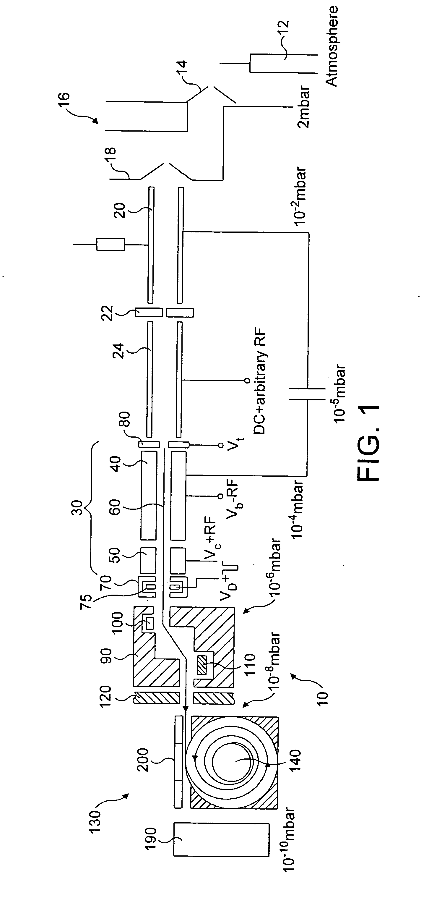
[0047] Referring first to FIG. 1, a mass spectrometer 10 is shown. The mass spectrometer comprises a continuous or pulsed ion source 12, such as an electron impact source, an electro-spray source (with or without a collisional RF multipole), a matrix-assisted laser desorption and ionisation (MALD) source, again with or without a collisional RF multipole, and so forth. In FIG. 1, an electrospray ion source 12 is shown.

[0048] The nebulized ions from the ion source 12 enter an ion source block 16 having an entrance cone 14 and an exit cone 18. As is described, for example, in WO 98 / 49710, the exit cone 18 has an entrance at 90° to the ion flow in the block 16 so that it acts as a skimmer to prevent streaming of ions into the subsequent mass analysis components.

[0049] A first component downstream of the exit cone 18 is an ion cooler 20 which reduces the energy of the sample ions from the ion source 12. Cooled ions exit the ion cooler 20 through an aperture 22 and arrive at a quadrupol...


PUM

PropertyMeasurementUnit
internal radiusaaaaaaaaaa
mass spectrometeraaaaaaaaaa

Abstract

A mass spectrometer 10 comprises an ion source 12 which generates nebulized ions which enter an ion cooler 20 via an ion source block 16. Ions within a window of m / z of interest are extracted via a quadrupole mass filter 24 and passed to a linear trap 30. Ions are trapped in a potential well in the linear trap 30 and are bunched at the bottom of the potential well adjacent an exit segment 50. Ions are gated out of the linear trap 30 into an electrostatic ion trap 130 and are detected by a secondary electron multiplier 10. By bunching the ions in the linear trap 30 prior to ejection, and by focussing the ions in time of flight (TOF) upon the entrance of the electrostatic trap 130, the ions arrive at the electrostatic trap 130 as a convolution of short, energetic packets of similar m / z. Such packets are particularly suited to an electrostatic trap because the FWHM of each packet's TOF distribution is less than the period of oscillation of those ions in the electrostatic trap.

Description

CROSS-REFERENCE TO RELATED APPLICATIONS [0001] This application is a continuation of co-pending U.S. patent application Ser. No. 10 / 472,917, filed Sep. 23, 2003, entitled “Mass Spectrometry Method and Apparatus,” which is a national stage application under 35 U.S.C. §371 of PCT Application No. PCT / GBO2 / 01373, filed Mar. 20, 2002, entitled “Mass Spectrometry Method and Apparatus,” which claims the priority benefit of United Kingdom Patent Application Nos. 0107280.8, filed Mar. 23, 2001 and 0126764.0, filed Nov. 7, 2001, which applications are incorporated herein by reference in their entireties.FIELD OF INVENTION [0002] This invention relates to a method and an apparatus of mass spectrometry, and in particular to a method and an apparatus for storage and injection of ions into an electrostatic ion trap. BACKGROUND OF THE INVENTION [0003] Mass spectrometers have been used to analyse a wide range of materials, including organic substances such as pharmaceutical compounds, environmental...

Claims


Application Information

Patent Timeline
Patent Type & Authority Applications(United States)
IPC IPC(8): H01J49/06G01N27/62H01J49/40H01J49/42
CPCB82Y30/00H01J49/425H01J49/423H01J49/4225
Inventor MAKAROV, ALEXANDERHARDMAN, MARK E.
Owner THERMO FINNIGAN
Why Eureka
Try Eureka