Water-developable infrared-sensitive printing plate

a technology of infrared-sensitive printing plate and water-developable element, which is applied in the field of imageable elements, can solve the problems of difficult formulation of appropriate imageable layers for water-developable printing plate precursors, and high cost of substantial quantities of used developer

Active Publication Date: 2005-06-09
KODAK POLYCHROME GRAPHICS
View PDF49 Cites 228 Cited by
  • Summary
  • Abstract
  • Description
  • Claims
  • Application Information

AI Technical Summary

Problems solved by technology

Because of high pH and the presence of organic solvents, disposal of substantial quantities of used developer is expensive and can cause environmental problems.
Processing of the imaged element in a chemical developer also introduces additional costs in the cost of the developer, the cost of the processing equipment, and the labor costs for operating the process.
However, appropriate imageable layers for water-developable printing plate precursors are difficult to formulate, and a need remains for a precursor that is readily developable but provides acceptable press performance.

Method used


Image

  • Water-developable infrared-sensitive printing plate
  • Water-developable infrared-sensitive printing plate
  • Water-developable infrared-sensitive printing plate

Examples


example 1

Synthesis of Copolymer 1

[0124] A mixture of 15 g PEGMA, 48 g water and 192 g 1-propanol was charged into a 500-mL flask, which was heated to 80° C. In a separate beaker, 66.9 g styrene and 0.48 g VAZO-64 were mixed, and part of this solution (12 g) was added to the mixture in the flask, which became hazy within about 10 minutes. Subsequently, the remaining solution was added to the flask over a 30-min period. After 3 additional hours, the resulting polymer solution contained 25 wt.-% solid of Copolymer 1.

[0125] Particle size of the polymer was measured using a MICROTRAC UPA150 ultrafine particle size analyzer available from Microtrac (North Largo, Fla.). Molecular weight was determined using gel permeation chromatography in dimethylformamide (“DMF”). Data are shown in Table 1.

[0126] In the table, “ma” is the mean diameter of the area distribution; “mv” is the mean diameter of the volume distribution, and represents the “center of gravity” of the distribution. The calculation of m...

example 2

Synthesis of Copolymer 2

[0128] A mixture of 54 g n-propanol and 16 g deionized water was charged into a 250-mL flask, which was heated to 70° C., purged with a steady flow of N2 gas, and stirred with a mechanical stirrer. A mixture of 54 g n-propanol, 16 g deionized water, 10 g PEGMA, 6.75 g styrene, 38.25 g acrylonitrile, and 0.48 g VAZO-64 was prepared in a separate beaker and added to the 250-mL flask dropwise over a period of 30 min. About 2.5 hours later, 0.16 g VAZO-64 was added to the reaction mixture. The polymerization reaction continued for a total of 19 hours. The resulting polymer solution contained 24 wt.-% solid of Copolymer 2.

Preparation of Printing Plate Precursors and Printing Plates

examples 3-6

Printing Plates Prepared using Copolymer I

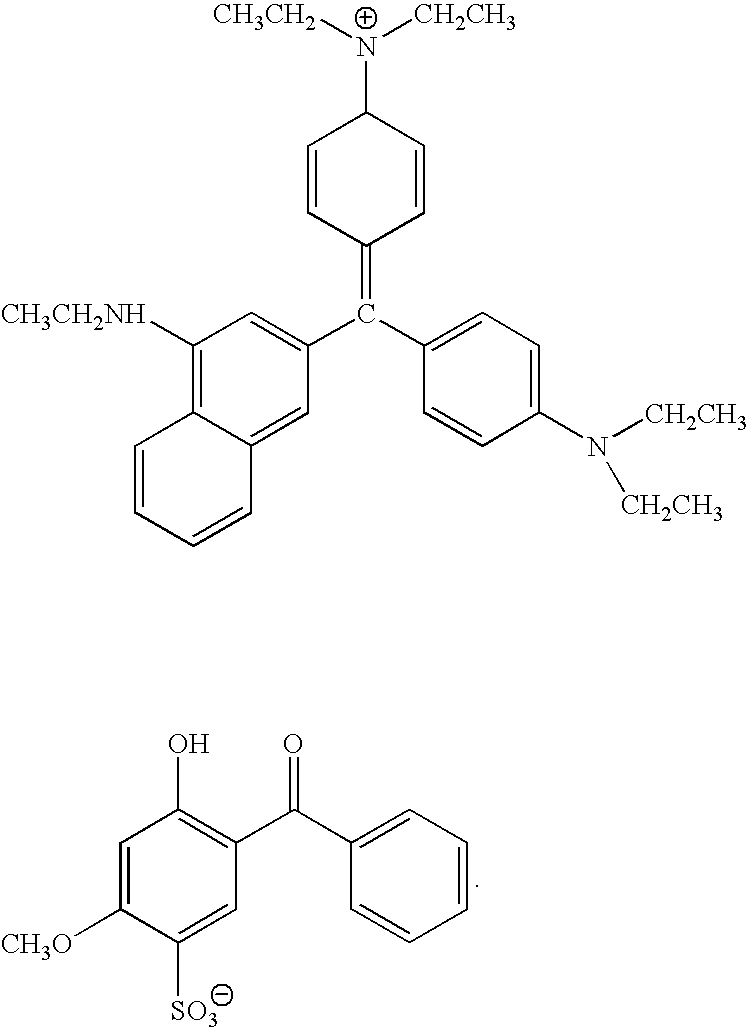
[0129] Coating compositions were prepared according to the formulations shown in Table 2. For Example 3, the Contrast Dye is Basonyl Violet 610. For Example 4, the Contrast Dye is Eosin B. For Example 5, the Contrast Dye is D11. For Example 6, the Contrast Dye is Quinaldine Red.

[0130] Each coating composition was applied to a brush-grained and phosphoric acid-anodized aluminum substrate that had been post-treated with poly(acrylic acid) (“PAA”). The coating composition was applied using a wire-wound rod and then dried for approximately 60 sec in a Ranar conveyor oven set at 94° C., to yield a printing plate precursor. The dry coating weight obtained was 1.0 g / m2.

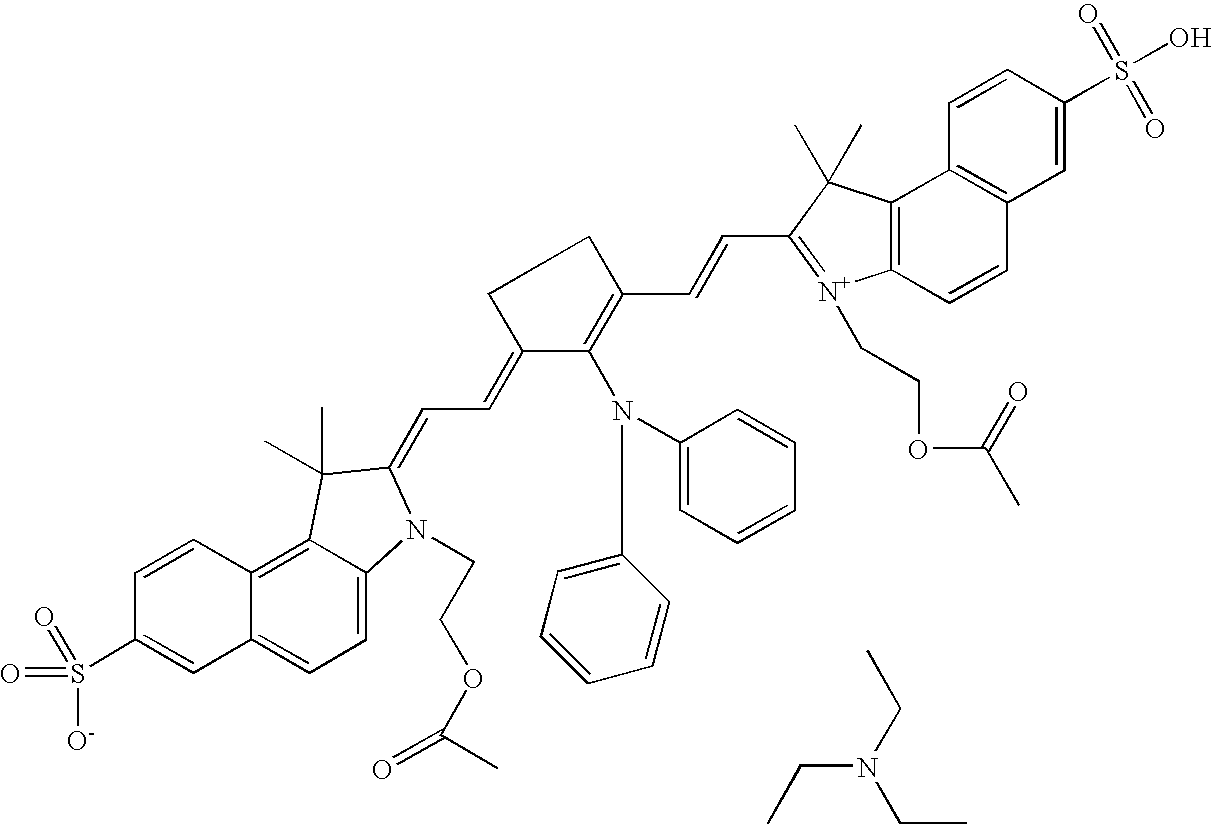
TABLE 2Formulation for coating compositions used in Examples 3-6.ComponentParts by WeightUrethane Acrylate2.20SARTOMER 3550.22Copolymer 117.56IRGACURE 2500.28IR Dye A0.04Mercapto-3-triazole0.12Contrast Dye20.01BYK 3360.60KLUCEL M4.41n-Propanol71.13Water13.62

1Copolymer 1 as used i...


PUM

PropertyMeasurementUnit
diameteraaaaaaaaaa
diameteraaaaaaaaaa
temperatureaaaaaaaaaa

Abstract

The present invention provides an imageable element including a lithographic substrate and an imageable layer disposed on the substrate. The imageable layer includes a radically polymerizable component, an initiator system capable of generating radicals sufficient to initiate a polymerization reaction upon exposure to imaging radiation, and a polymeric binder having a hydrophobic backbone and including constitutional units having a pendant group including a hydrophilic poly(alkylene oxide) segment. The imageable element can be developed using an aqueous developer solution. Alternatively, the imageable element can be developed on-press by contact with ink and / or fountain solution.

Description

REFERENCE TO RELATED APPLICATION [0001] This application is a continuation-in-part of U.S. patent application Ser. No. 10 / 891,727 filed Jul. 15, 2004, and entitled “Preparation of Solvent-Resistant Binder for an Imageable Element,” the disclosure of which is incorporated herein by reference in its entirety. This application is a continuation-in-part of U.S. patent application Ser. No. 10 / 872,209 filed Jun. 17, 2004, and entitled “Imageable Element with Solvent-Resistant Polymeric Binder,” the disclosure of which is incorporated herein by reference in its entirety. This application is a continuation-in-part of U.S. patent application Ser. No. 10 / 119,454 filed Apr. 10, 2002, the disclosure of which is incorporated herein by reference in its entirety.TECHNICAL FIELD [0002] The present invention relates to imageable elements useful as lithographic printing plate precursors. In conventional or “wet” lithographic printing, ink-receptive regions, known as image areas, are generated on a hy...

Claims


Application Information

Patent Timeline
Patent Type & Authority Applications(United States)
IPC IPC(8): B41C1/10B41M5/36G03F7/021G03F7/033
CPCB41C1/1008G03F7/0212G03F7/033B41C2210/24B41C2210/08B41C2210/20B41C2210/22B41C2210/04
Inventor MUNNELLY, HEIDI M.WIELAND, KEVINRAY, KEVIN BARRY
Owner KODAK POLYCHROME GRAPHICS
Why Eureka
Try Eureka