Ultrahigh-frequency light source using dual-wavelength laser with 3-dB beam splitter and method of manufacturing the same

a dual-wavelength laser and ultra-high-frequency technology, applied in semiconductor lasers, cladded optical fibres, instruments, etc., can solve the problems of high cost, inability to change the interval between two lasing wavelengths, and limited transmission distance of electrical approaches in the range of microwave or millimeter waves, etc., to achieve stable generation of two wavelengths, facilitate manufacturing, and simple structure

Active Publication Date: 2005-06-16
ELECTRONICS & TELECOMM RES INST
View PDF3 Cites 23 Cited by
  • Summary
  • Abstract
  • Description
  • Claims
  • Application Information

AI Technical Summary

Benefits of technology

[0016] A light source according to the present invention has a semiconductor laser structure capable of stably generating two wavelengths. The light source can adjust a detuning of two wavelengths generated by an electrode applying a voltage or a current to two waveguide gratings or a micro heater applying heat to the two waveguide gratings so that the light source is tunable and generates ultrafast optical signals. In addition, the light source of the present invention has a simple structure so that holography instead of e-beam lithography may be used, thereby facilitating manufacturing. Since the operations of elements included in the light source can be independently controlled from an outside, a yield can be increased.

Problems solved by technology

However, electrical approaches in the range of microwaves or millimeter waves are limited in a transmission distance and incur high expenses.
However, the proposed structure does not allow the mode interval between two lasing wavelengths to be changed, requires conditions for reliable lasing operation, complicates manufacturing processes since e-beam lithography is required to periodically shift the phase of a grating.
However, the device requires very critical conditions to maintain the intensities of two lasing optical signals the same.
Moreover, it is impossible to continuously change a wavelength interval (i.e., detuning) between two lasing signals,.
15-17, 1999] can continuously adjust an interval between lasing wavelengths, but intensity of light having two lasing wavelengths is not uniform.

Method used


Image

  • Ultrahigh-frequency light source using dual-wavelength laser with 3-dB beam splitter and method of manufacturing the same
  • Ultrahigh-frequency light source using dual-wavelength laser with 3-dB beam splitter and method of manufacturing the same
  • Ultrahigh-frequency light source using dual-wavelength laser with 3-dB beam splitter and method of manufacturing the same

Examples


Embodiment Construction

[0022] The present invention will now be described more fully with reference to the accompanying drawings, in which exemplary embodiments of the invention are shown. The invention may, however, be embodied in many different forms and should not be construed as being limited to the embodiments set forth herein; rather, these embodiments are provided so that this disclosure will be thorough and complete, and will fully convey the concept of the invention to those skilled in the art. Like reference numerals in the drawings denote like elements.

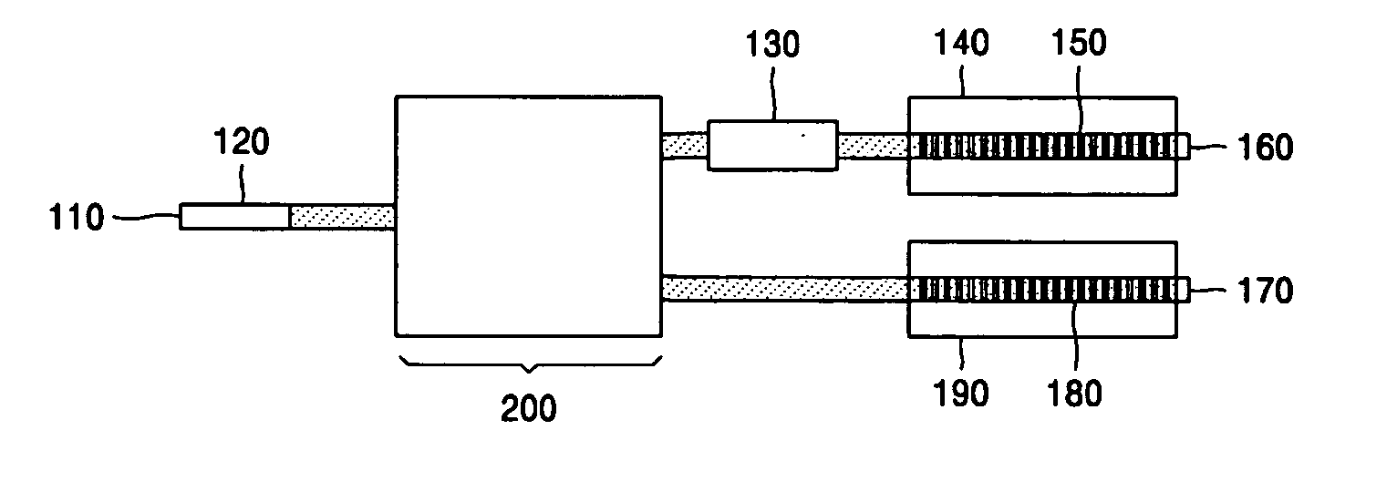
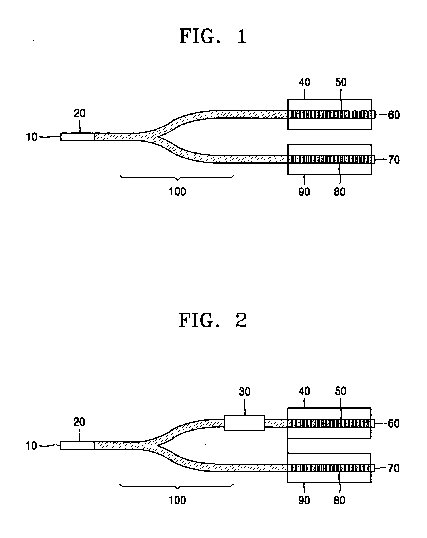
[0023] Referring to FIG. 1, a light source according to a first embodiment of the present invention has a structure in which a 3-dB Y-branch 100 is integrated into a Febry-Perot laser diode 20. The structure may be implemented by manufacturing the Febry-Perot laser diode 20 and the Y-branch 100 in either monolithic or hybrid form. More specifically, the Febry-Perot laser diode 20 and the Y-branch 100 may be integrated using butt-coupling, evanes...


PUM


Abstract

A light source has a structure in which a 3-dB beam splitter is integrated with a Febry-Perot laser diode having a cleaved plane. A first waveguide grating and a first refractive index modifier changing a Bragg wavelength of the first waveguide grating are provided at one branch of the 3-dB beam splitter. A second waveguide grating and a second refractive index modifier changing a Bragg wavelength of the second waveguide grating are provided at another branch of the 3-dB beam splitter.

Description

BACKGROUND OF THE INVENTION [0001] This application claims the priority of Korean Patent Application No. 2003-91340, filed on Dec. 15, 2003, in the Korean Intellectual Property Office, the disclosure of which is incorporated herein in its entirety by reference. [0002] 1. Field of the Invention [0003] The present invention relates to a semiconductor light source which generates ultrafast optical signals using beats of a dual-wavelength laser, and more particularly, to a tunable light source capable of continuously adjusting an interval between two wavelengths, and a method of manufacturing the same. [0004] 2. Description of the Related Art [0005] Microwaves or millimeter waves through optical fiber have been researched since they can be applied to wireless access networks and phase array antennas. However, electrical approaches in the range of microwaves or millimeter waves are limited in a transmission distance and incur high expenses. Unlikely, light in a THz range transmits non-li...

Claims


Application Information

Patent Timeline
Patent Type & Authority Applications(United States)
IPC IPC(8): G02B6/02G02B6/28G02B6/26H01S5/06H01S5/062H01S5/10H01S5/14
CPCG02B6/02195G02B6/2804G02B6/2813H01S5/0612H01S5/146H01S5/1003H01S5/1096H01S5/141H01S5/0623G02B6/28
Inventor KIM, DONG CHURLYEE, DAE SULEEM, YOUNG AHNPARK, KYUNG HYUN
Owner ELECTRONICS & TELECOMM RES INST
Why Eureka
Try Eureka