Digital regulated light receive module and regulation method

a technology of digital regulated light and receive module, which is applied in the direction of pulse technique, transmission monitoring, instruments, etc., can solve the problems of potentiometer itself, inability to fully compensate for the temperature characteristics of different apd, and inability to track the bias voltage v_apd, etc., to achieve better stability and reliability, easy to test, and longer life

Inactive Publication Date: 2005-06-16
APEX NET LLC
View PDF4 Cites 22 Cited by
  • Summary
  • Abstract
  • Description
  • Claims
  • Application Information

AI Technical Summary

Benefits of technology

[0065] (1) Better stability and reliability. Since a digital adjusting unit (a digital potentiometer or a D / A converter) does not have mechanical contacts, it is more reliable, stable and with longer life.
[0066] (2) Easier to test and lower production cost. Since a digital adjusting unit is adjusted by software, it is easier to test and adjust the bias voltage of an optical detector.
[0067] (3) Easier to trace products. Since parameters of an optical receiver module are stored in a memory, a product data is easier to store in a database and to trace.
[0068] (4) An optical receiver module is monitored on-line, so the maintenance cost is reduced.
[0069] (5) It is more effective that the dark current compensation and temperature compensation of an optical receiver module, its receiving sensitivity and detecting accuracy are raised.

Problems solved by technology

˜+0.15V / ° C. In convention, a temperature transducer connected externally is used, and its output voltage regulates the feedback voltage Vfb to obtain different V_APD bias voltages; but during in use, it is impossible to track the bias voltage V_APD, namely it is unable to compensate fully different APD temperature characteristics.
Nevertheless, adjustment of each parameters in this module is all implemented by potentiometers, and a potentiometer itself has disadvantages, such as low reliability, parameter drift caused by age etc.
; besides, the parameters cannot be monitored and adjusted in real time and adjustment of parameters can only be done manually, which depends on skills of workers.
In this way, production efficiency is low and non-linear compensation characteristic is bad.
(1) Adjustment procedure of parameters is complicated and expensive, and maintainability of parameters online is bad.
Since a mechanical contact has problems of contact fault and bad temperature characteristic, also during transportation and vibration a mechanical contact will drift, so the parameters of an optical receiver module are drifted too.
Adjusting and testing a potentiometer is a complicated procedure, and this makes it difficult to put the optical receiver module production into automation, so it is difficult to reduce the production cost.
Adjusting and testing an optical receiver module highly depend on skill of a worker, so it is difficult to keep consistence of products.
Aging will cause drift of parameters, and in an optical receiver module with analog adjustment, it is impossible to make an online adjustment of the parameters without interrupting services, so the reliability and stability cannot well satisfy telecommunication equipment requirement.
(2) Parameters cannot be stored and sampled expediently, and the received optical power cannot be read out directly.
There is no any memory to store parameters, such as the initial bias voltage at adjustment, receiving sensitivity and the date of adjustment etc., so it is impossible to obtain those parameters online.
(3) Nonlinear compensation is bad.
The temperature compensation mainly depends on a thermistor, and actual compensation is inconsistent with that of a ADP because of the thermistor temperature characteristic, so that key performances of the module such as receiving sensitivity get worse.

Method used


Image

  • Digital regulated light receive module and regulation method
  • Digital regulated light receive module and regulation method
  • Digital regulated light receive module and regulation method

Examples


Embodiment Construction

[0080] The invention will be described in more detail with reference to drawings.

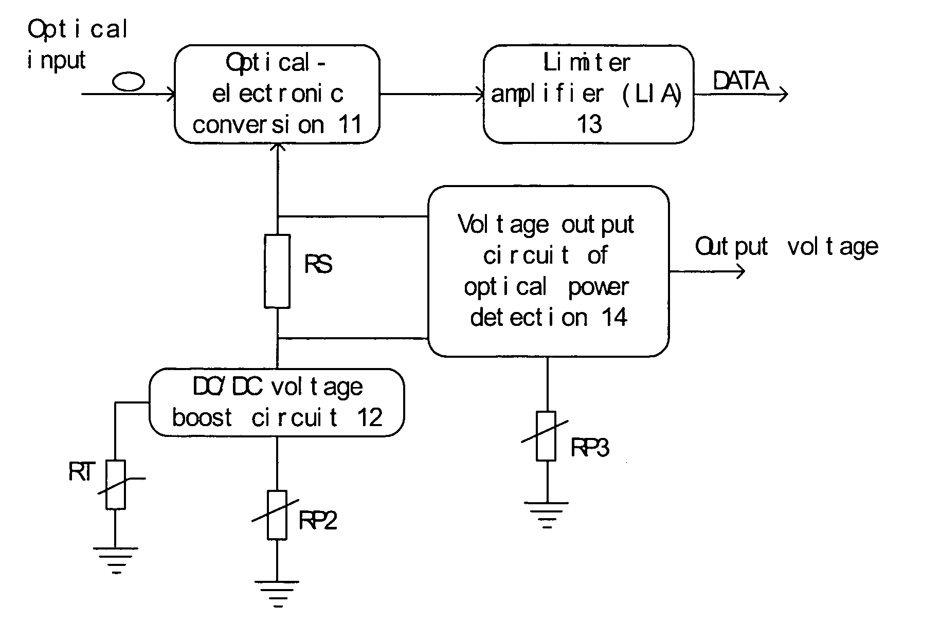
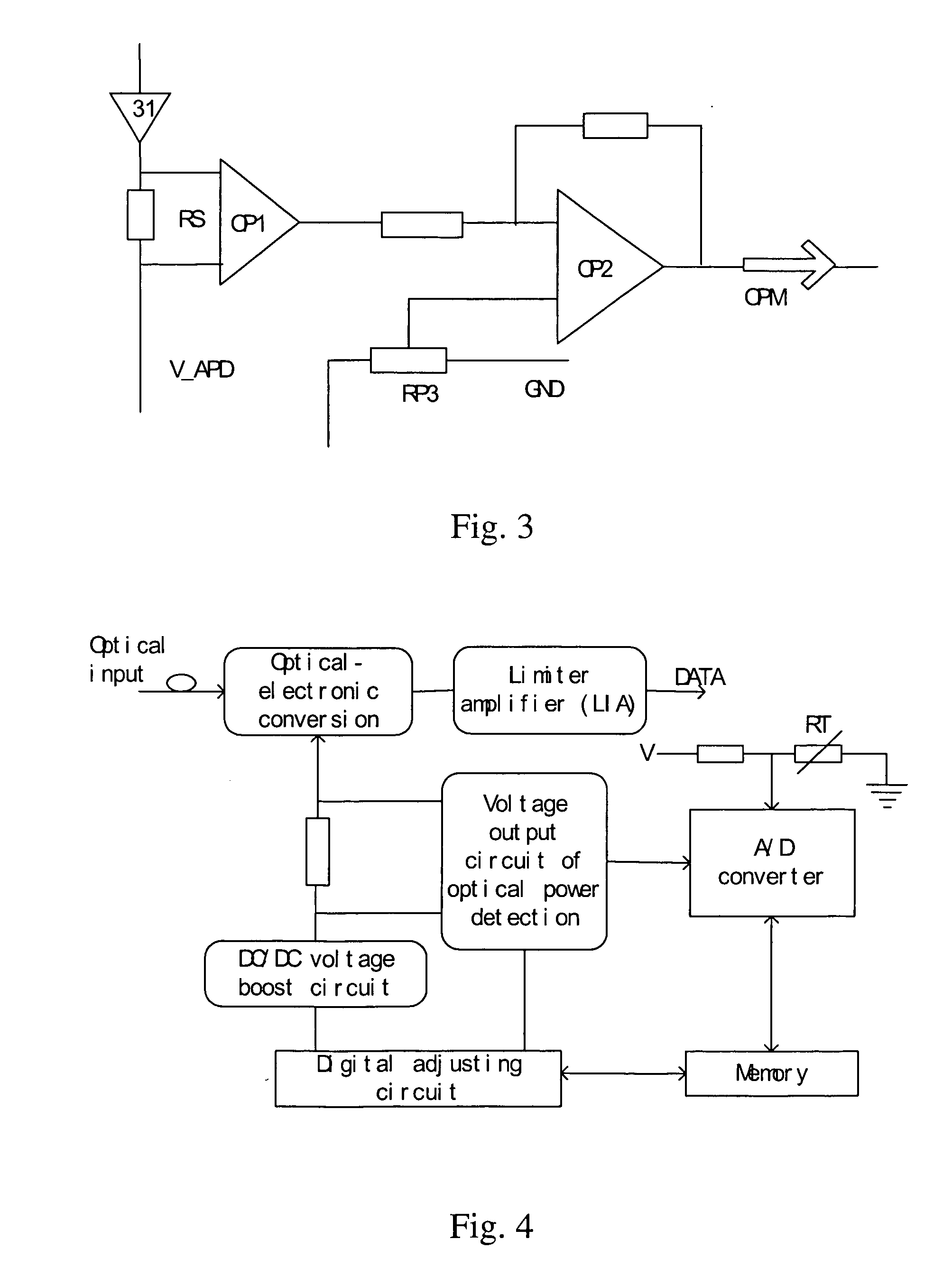
[0081]FIG. 4 shows a diagram of a digital optical receiver module. The digital optical receiver module includes elements as follow: an optical-electronic conversion circuit 21, a DC / DC voltage boost circuit 22, a limiter amplifier 23 (LIA), a voltage output circuit of optical power detection 24, a digital adjusting circuit 25, an analog-digital converter (A / D or ADC) 26 and a memory 27. Comparing with the analog optical receiver module, shown in FIG. 1, a digital adjusting circuit 25, an A / D converter 26 and a memory 27 are added in the digital optical receiver module. A thermistor RT measures the optical detector temperature for compensation through the bias voltage.

[0082] The optical-electronic conversion circuit 21 converses a received optical signal into an electrical signal that is amplified by the limiter amplifier 23 and outputted, as shown with DATA in FIG. 4. The A / D converter 26 converts the...


PUM


Abstract

The invention discloses a digital adjusting method for an optical receiver module, and the method implements real-time monitor of parameters, on-line adjustment and non-linear compensation. The digital optical receiver module includes elements as follow: a voltage output circuit of optical power detection 24, a DC/DC voltage boost circuit 22 and a bias voltage adjusting unit which is consisted of an optical-electronic conversion circuit 21; a digital adjusting unit 25, an analog-digital converter (A/D converter) 26 and a memory 27. The digital adjusting unit 25, which is a D/A converter or a digital potentiometer, is used to make on-line adjustment and to implement temperature compensation and dark current compensation of the optical receiver module. The A/D converter 26 is used to monitor the optical power, the working temperature and the bias voltage of the optical detector in real time. The memory 27 is used to store parameters of the optical receiver module for comparison with a detected optical power and measured temperature etc. and for on-line interrogation.

Description

FIELD OF THE TECHNOLOGY [0001] The invention relates generally to an optical-electrical conversion technique in an optical network communication system, more specifically to an optical receiver module and a method for digitally adjusting its parameters. BACKGROUND OF THE INVENTION [0002] In an optical communication system, an optical receiver module converts optical signals into electronic signals, and its performance directly affects performance and stability of an optical communication system. [0003]FIG. 1 shows a conventional analog optical receiver module with analog adjustment, which mainly includes three parts. [0004] (1) An optical-electronic conversion circuit 11, which has an optical signal input and a weak electronic signal output, adopts a PIN-Photodiode detector or an Avalanche Photodiode detector (APD) or an optical detector; and a limiter amplifier (LIA) 13 amplifies the weak electronic signal limitedly to extract data and clock signal. [0005] (2) A bias voltage adjust...

Claims


Application Information

Patent Timeline
Patent Type & Authority Applications(United States)
IPC IPC(8): H04B10/69
CPCH04B10/6911
Inventor TANG, ZHENYU
Owner APEX NET LLC
Why Eureka
Try Eureka