Method and device for automated layer generation for double-gate FinFET designs

a technology of double-gate finfet and automatic layer generation, which is applied in the field of field effect transistors, can solve the problems of affecting the design of existing designs based on non-finfet technology, the formation of said sidewall spacers, and the violation of electronic properties exemplary design rules,

Inactive Publication Date: 2005-06-23
IBM CORP
View PDF5 Cites 59 Cited by
  • Summary
  • Abstract
  • Description
  • Claims
  • Application Information

AI Technical Summary

Benefits of technology

[0017] In order to solve the above mentioned objective, it has first been realized that the above discussed technical problem with interfering fin structures of two ore more contiguous design regions can be solved by proceeding or passing over from a present hierar

Problems solved by technology

In other words, only the combination of surface topography and dry etching inevitably leads to the formation of said sidewall spacers.
These changes in electronic properties represent an exemplary design rule violation.
Further, as another requirement for the design of an underlying structure, an already existing design based on non-FinFET technology must not be changed pa

Method used


Image

  • Method and device for automated layer generation for double-gate FinFET designs
  • Method and device for automated layer generation for double-gate FinFET designs
  • Method and device for automated layer generation for double-gate FinFET designs

Examples


Embodiment Construction

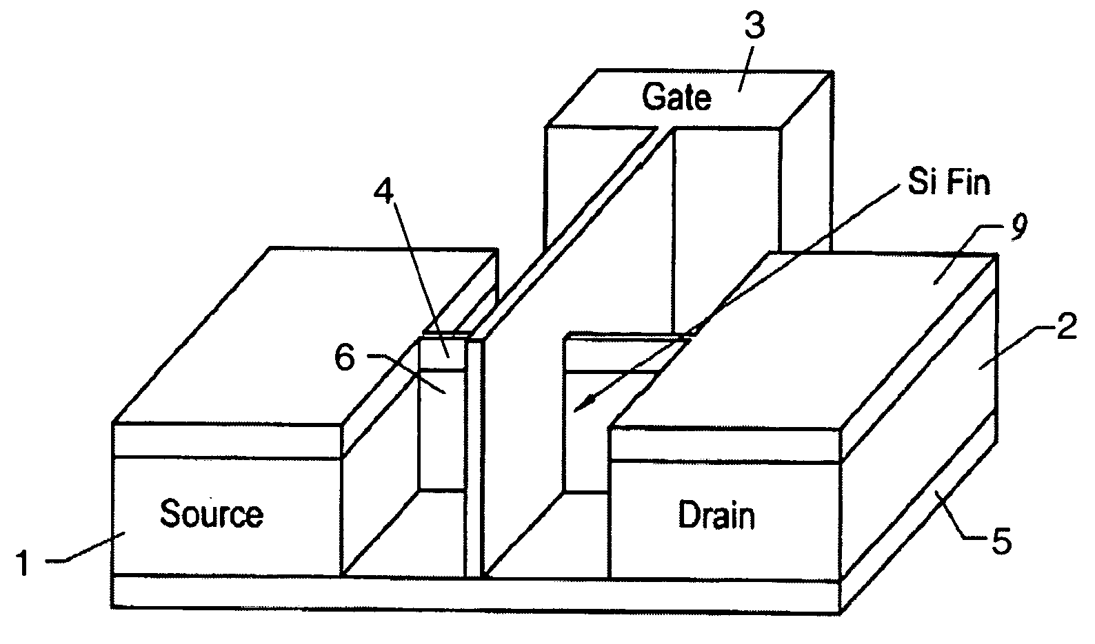
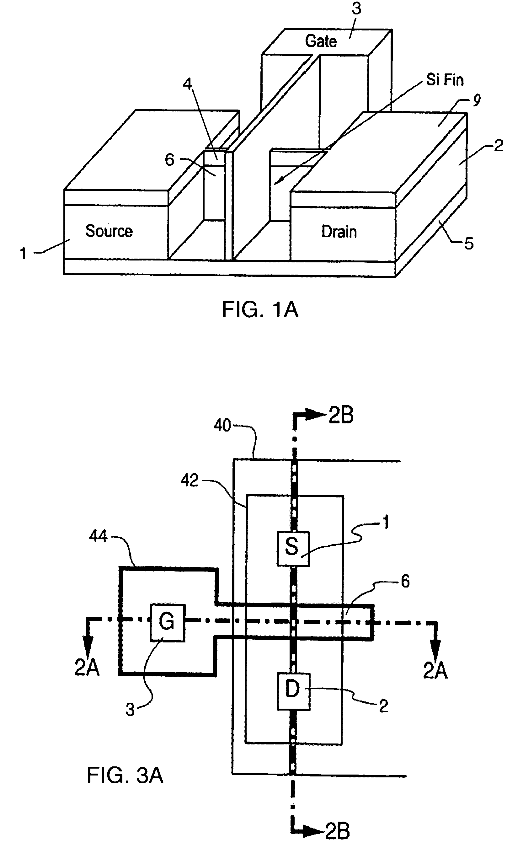
[0032] Referring to the drawing, FIG. 1A illustrates in perspective a typical fin structure (in the present example a FET) in accordance with a known prior art approach. Such a planarized silicon fin device is disclosed e.g. in U.S. Pat. No. 6,252,284 by Paul Muller et al., assigned to the present assignee, issued Jun. 26, 2001. A corresponding double-gated FinFET transistor structure is disclosed e.g. in U.S. Pat. No. 6,413,802 assigned to University of California and issued Jul. 2, 2002.

[0033] In the structure shown in FIG. 1A, the device is fabricated on insulating layer 5, e.g. a Silicon-on-Insulator (SoI) substrate, and includes a silicon drain island 2 and a source island 1 connected by a silicon fin or channel 6. The source, drain and channel are covered by a dielectric layer 9 (hard mask), and a gate 3 extends across the channel fin 4 and is isolated therefrom by gate oxide and the hard mask. The channel 6 extends horizontally on the substrate 5 with the gates in planes on ...


PUM


Abstract

In a FinFET integrated circuit design, a combined cell structure contains two single cell structures at a first design hierarchy having fin shapes, the cell structures are placed adjacent to each other. The combined fin shapes of the two single cell structures at the first design hierarchy lead to a violation of a design rule related to fin topology in the overlapping region. A fin generation tool thus decides not to place the fins in the first design hierarchy. The fin generation is delegated another design hierarchy resulting in the generation of a single combined fin for both single cells.

Description

REFERENCED DOCUMENTS [0001] U.S. Pat. No. 6,252,284 B1, assigned to the present assignee and relating among others to a process for fabricating a planarized silicon fin device according to the present invention, is regarded to be fully incorporated herein by reference. [0002] Further, an article by the present inventors, entitled “FinFET Technology for Future Microprocessors ” and published in 2003 IEEE International SOI Conference, Newport Beach, Calif., page 33-34, ISBN 0-7803-7815-6, is also regarded to be fully incorporated herein by reference. FIELD OF THE INVENTION [0003] The present invention generally relates to Field Effect Transistors (FETs) as well as to Metal-Oxide Semiconductor (MOS) and Complementary Metal-Oxide Semiconductor (CMOS) devices and their chip design. More specifically, the invention concerns a method and device for designing an according device structure particularly including double-gate fin based field-effect transistor (FinFET) technology and a method a...

Claims


Application Information

Patent Timeline
IPC IPC(8): G06F17/50H01L21/336G03F1/08H01L21/82H01L21/8234H01L27/04H01L27/08H01L27/088H01L29/786
CPCG06F17/5068H01L29/785H01L29/66795H01L21/823821G06F30/39H01L27/04
Inventor ALLER, INGOGERNHOEFER, VEITKEINERT, JOACHIMLUDWIG, THOMAS
Owner IBM CORP
Why Eureka
Try Eureka