

Textured balloons
- Summary
- Abstract
- Description
- Claims
- Application Information
AI Technical Summary
Benefits of technology
Problems solved by technology
Method used
Image

Examples
Embodiment Construction
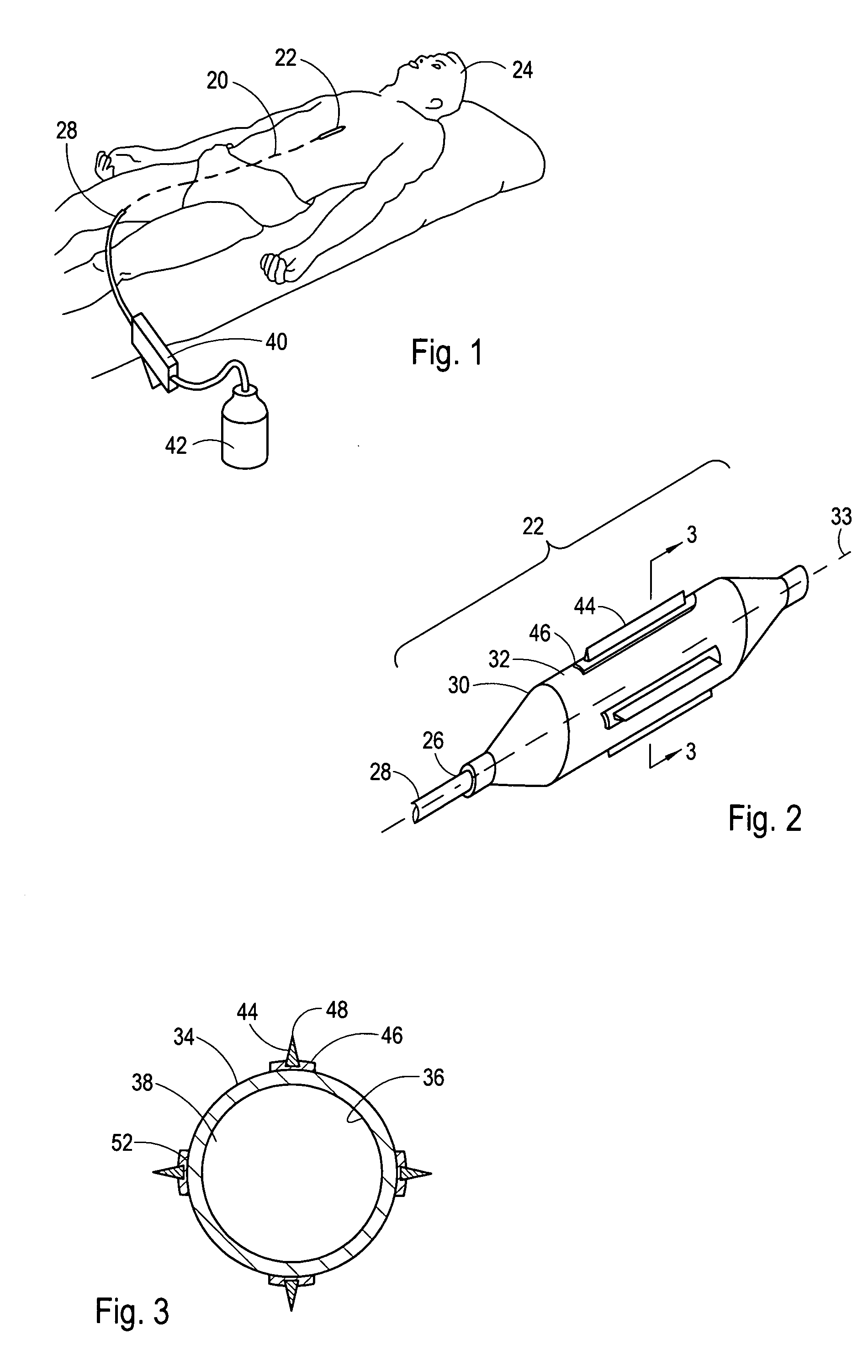
[0025] Referring initially to FIG. 1, a catheter 20 having an incising device, which in this case is a cutting balloon 22, is shown for performing a medical procedure at an internal treatment site of a patient 24. More specifically, the catheter 20 is shown positioned to treat a lesion in an upper body artery. Although the catheter 20 is capable of performing a medical procedure in an upper body artery such as a coronary artery, those skilled in the pertinent art will recognize that the use of the catheter 20 as herein described is not limited to use in a specific artery, but, instead can be used in vascular conduits and other ductal systems throughout the human body.
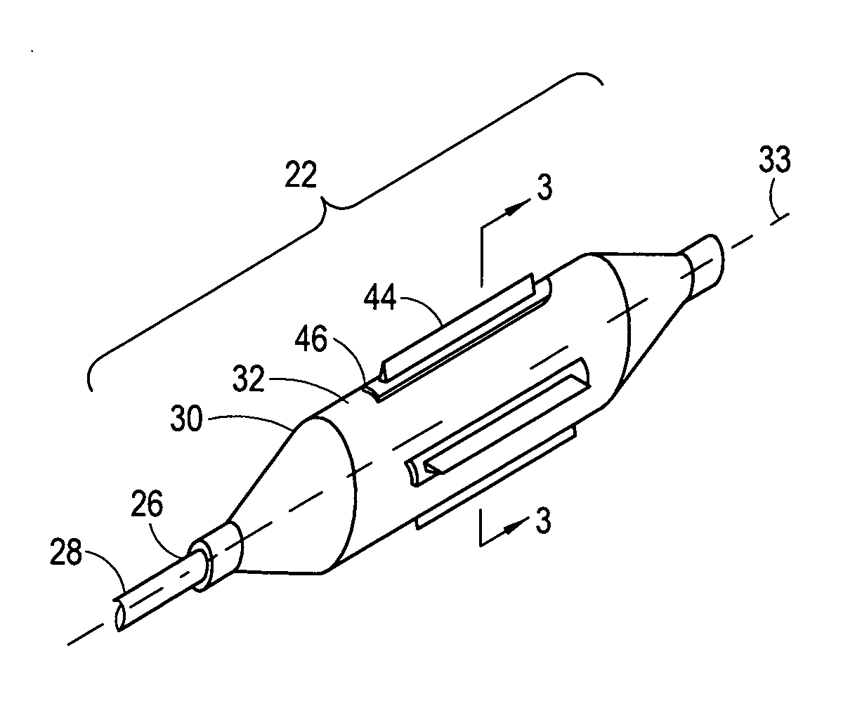
[0026] Referring now to FIG. 2, the distal portion of the catheter 20 is shown to include a cutting balloon 22 that is attached to the distal end 26 of an inflation tube 28. FIG. 2 further shows that the cutting balloon 22 can include an inflatable balloon 30 that typically includes a cylindrical shaped working section...
PUM
 Abstract
Description
Claims
Application Information