Stiffened surface micromachined structures and process for fabricating the same

Inactive Publication Date: 2005-06-30
MONTANA STATE UNIVERSITY
View PDF9 Cites 95 Cited by
  • Summary
  • Abstract
  • Description
  • Claims
  • Application Information

AI Technical Summary

Benefits of technology

[0018] The micromachined devices built with vertical features or fins or ribs created by molding the substrate and backfilling the mold with silicon nitride exhibit increased out-of-plane bending stiffness. The increased bending stiffness resulting from stiffening fins or ribs substantially reduce stress-related deformations experienced by surface-micromachi

Problems solved by technology

This presents significant problems for the design of micromechanical mirrors.
These mirrors may require diameters of several hundred micrometers, leading to very large length-to-thickness ratios.
Deformation of the mirror surface translates to aberrations of the optical beam, leading to large insertion loss in the case of an optical switch and poor fidelity in an imaging system.
Complex and exotic processes increase the production costs and reduce the yield, raising the ultimate cost of the cross connect.
Bulk micromachining has produced flat silicon mirrors with large deflection angles, but uses complicated proces

Method used


Image

  • Stiffened surface micromachined structures and process for fabricating the same
  • Stiffened surface micromachined structures and process for fabricating the same
  • Stiffened surface micromachined structures and process for fabricating the same

Examples


Embodiment Construction

[0040] Reference will now be made in detail to the preferred embodiments of the present invention, examples of which are illustrated in the accompanying drawings. It is to be understood that the figures and descriptions of the present invention included herein illustrate and describe elements that are of particular relevance to the present invention, while eliminating, for purposes of clarity, other elements found in a typical micromachining process or micromachined device.

[0041] It is worthy to note that any reference in the specification to “one embodiment” or “an embodiment” means that a particular feature, structure or characteristic described in connection with the embodiment is included in at least one embodiment of the invention. The appearances of the phrase “in one embodiment” at various places in the specification do not necessarily all refer to the same embodiment.

Process Flow

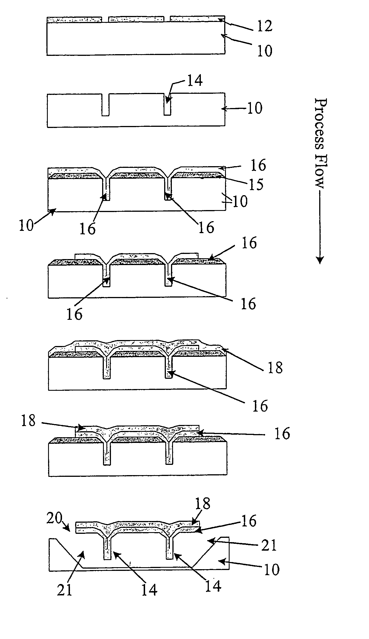
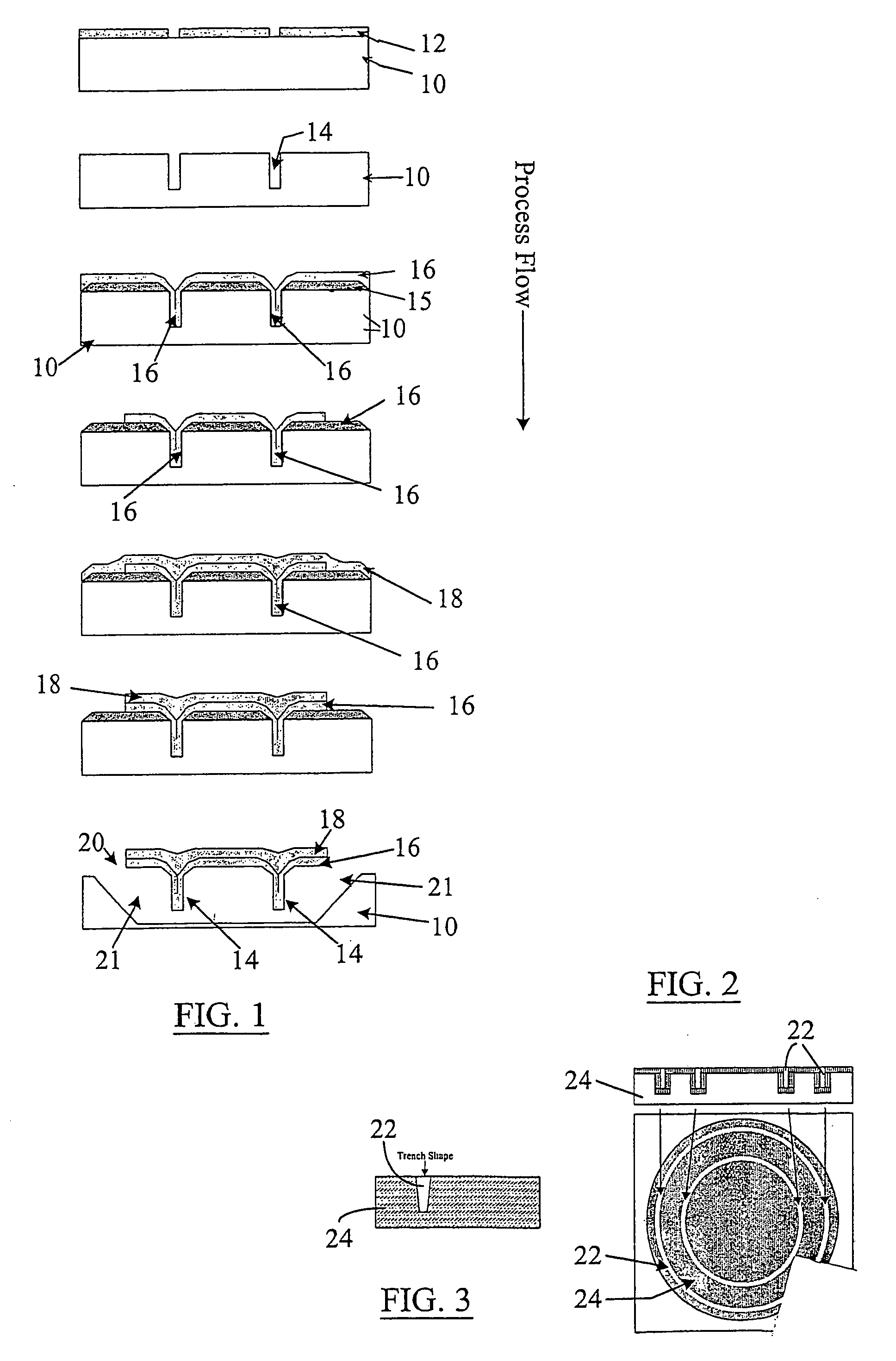
[0042]FIG. 1 illustrates an abbreviated fabrication process flow according to the present inv...


PUM

PropertyMeasurementUnit
Lengthaaaaaaaaaa
Lengthaaaaaaaaaa
Lengthaaaaaaaaaa

Abstract

Stiffened surface micromachined structures and a method to fabricate the same. A silicon substrate (10) is first etched to produce a mold containing a plurality of trenches or grooves (14) in a lattice configuration. Sacrificial oxide (15) is then grown on the silicon substrate (10) and then a stiffening member (16) (silicon nitride) is deposited over the surface of the substrate, thereby backfilling the grooves with silicon nitride. The silicon nitride is patterned to form mechanical members and metal (40) is then deposited and patterned to form the leads and capacitors for electrostatic actuation of mechanical members. The underlying silicon and sacrificial oxides are removed by etching the mold from underneath the fabricated micromachined devices, leaving free-standing silicon nitride devices with vertical ribs. The devices exhibit increased out-of-plan bending stiffness because of the presence of stiffening ribs. Silicon nitride biaxial pointing mirrors with stiffening ribs are also described.

Description

REFERENCE TO RELATED APPLICATIONS [0001] This application claims priority benefits of prior filed co-pending U.S. provisional patent application Ser. No. 60 / 330,433, filed on Oct. 22, 2001, the disclosure of which is incorporated herein by reference in its entirety.BACKGROUND [0002] 1. Field of the Invention [0003] The present invention generally relates to micromachined structures and their fabrication methods, and, more particularly, to a micromachined device with stiffening members to reduce stress-induced or inertial deformation and a method of fabricating the same. [0004] 2. Description of Related Art [0005] All publications and patent applications herein are incorporated by reference to the same extent as if each individual publication or patent application was specifically and individually indicated to be incorporated by reference. [0006] The Internet, cable television and teleconferencing has highlighted the increased requirement for communication bandwidth. The use of dense...

Claims


Application Information

Patent Timeline
IPC IPC(8): B01D29/00B81B3/00
CPCB81B3/007
Inventor DICKENSHEETS, DAVID LKAISER, TODD J.HIMMER, PHILIP A.LUTZENBERGER, JEFFREYFRIHOLM, ROBERT A.
Owner MONTANA STATE UNIVERSITY
Why Eureka
Try Eureka