
Electronics unit

a technology of electronic components and units, applied in the field of electronic units, can solve the problems of increasing power density and power loss of electronic power components in electronic units, overloading of electronic power components, and insufficient thermal conductivity of known heat-conducting adhesives, etc., and achieves good dissipation of lost heat, easy production, and simple construction

Inactive Publication Date: 2005-07-07
SIEMENS AG
View PDF10 Cites 0 Cited by
  • Summary
  • Abstract
  • Description
  • Claims
  • Application Information

AI Technical Summary

Benefits of technology

[0007] An object of the invention is to provide an electronics unit with a support and a ceramic substrate which has a simple construction, can be easily produced and permits very good dissipation of the lost heat generated by the electronic power components.
[0009] The thermal process, preferably under an inert gas atmosphere, produces a chemical bond between the two parts to be joined that is mechanically stable and has very good heat conduction. This good heat conduction of the film between the substrate and the support halves the thermal resistance in comparison with the known construction and considerably increases the service life of the electronic power components. This feature allows smaller, and consequently lower-cost, power components to be used, and / or reduces the number of components that is required to be used, which leads to a more compact construction of the electronics unit.
[0011] This allows good compensation for tolerances of the ceramic substrate and the support.
[0012] For good heat dissipation, the support has a thickness which corresponds to a multiple of the thickness of the ceramic substrate, the support preferably having a thickness of approximately ten times the thickness of the ceramic substrate.
[0015] A simple production of the power electronics unit may be achieved by applying a system of conductor tracks and / or insulating layers and / or resistors to the ceramic substrate using thick-film technology. More specifically, thick-film hybrid technology may be used to apply the system of conductor tracks and / or insulating layers and / or resistors. The electronic components may be soldered onto the system of conductor tracks in a reflow or vapor phase process.

Problems solved by technology

The power density and power losses of the electronic power components in electronics units have increased such that the thermal conductivity of known heat-conducting adhesives is no longer adequate to pass on the heat generated by the electronic power components adequately to the support for heat dissipation.
This leads to overloading of the electronic power components and consequently to high failure rates.

Method used


Image

  • Electronics unit
  • Electronics unit

Examples


Embodiment Construction

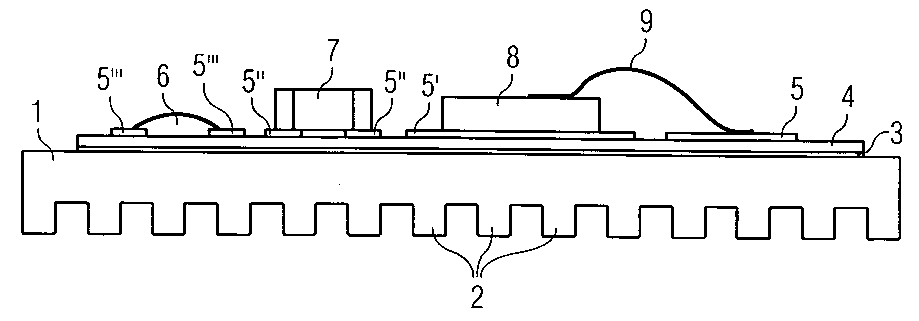
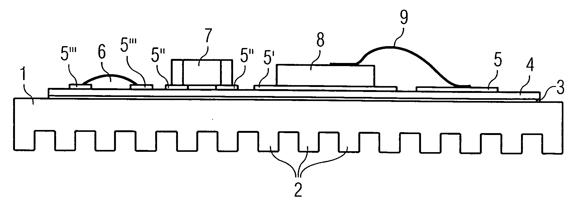
[0019] The electronics unit shown in the FIGURE has a support 1 in the form of a plate of aluminium or an aluminum alloy which is provided on its one side with cooling ribs 2. On the planar surface opposite from the cooling ribs 2, a film 3 of an aluminum-silicon alloy (AlSi film) with a thickness of 20 μm is applied in a thermal process under an inert gas atmosphere and chemically bonded to the support 1.

[0020] The surface of the ceramic substrate 4 facing away from the support 1 has conductor tracks 5, 5′, 5″ and 5′″, applied by thick-film technology. The conductor tracks 5, 5′, 5″ and 5′″ may, for example, comprise a copper coating. In this case, a thick-film resistor 6 is also applied to the conductor tracks 5′″, also by thick-film technology such as, for example, thick-film hybrid technology.

[0021] An electronic component 7 is soldered onto the conductor tracks 5″.

[0022] An electronic power component 8 is soldered onto the conductor track 5′ and is connected to the conductor...


PUM


Abstract

An electronics unit includes a support in the form of a plate of an aluminum alloy. A ceramic substrate is adhesively attached to the substrate. A system of conductor tracks on which electronic power components are arranged is applied to the ceramic substrate. A film of an aluminum-silicon alloy is arranged between the support and the ceramic substrate and is chemically bonded to the support and the ceramic substrate in a thermal process.

Description

BACKGROUND OF THE INVENTION [0001] 1. Field of the Invention [0002] The invention relates to an electronics unit with a support in the form of a plate of aluminum or an aluminum alloy, on which there is adhesively attached a ceramic substrate, which is provided with a system of conductor tracks on which electronic power components are arranged. [0003] 2. Description of the Related Art [0004] Electronics units used in automobile electronics have to withstand high ambient temperatures and adequately dissipate the lost heat of the electronic power components. In electronics units having support plates with an adhesively attached ceramic substrate, heat-conducting adhesives are used for the adhesive bonding of the ceramic substrate to the support. [0005] The power density and power losses of the electronic power components in electronics units have increased such that the thermal conductivity of known heat-conducting adhesives is no longer adequate to pass on the heat generated by the e...

Claims


Application Information

Patent Timeline
IPC IPC(8): H01L23/373H05K1/02H01L23/40H05K1/03H05K3/00H05K3/38
CPCH05K1/0306H05K3/0061H01L2924/19107H01L2924/19105H01L2224/73265H01L2224/48472H01L2224/48227H01L2224/48091H01L2224/32225H05K3/38H01L2924/00014H01L2924/00
Inventor THYZEL, BERND
Owner SIEMENS AG
Learn More