
Structure of an interleaving striped capacitor substrate

Inactive Publication Date: 2005-07-07
IND TECH RES INST
View PDF7 Cites 15 Cited by
  • Summary
  • Abstract
  • Description
  • Claims
  • Application Information

AI Technical Summary

Benefits of technology

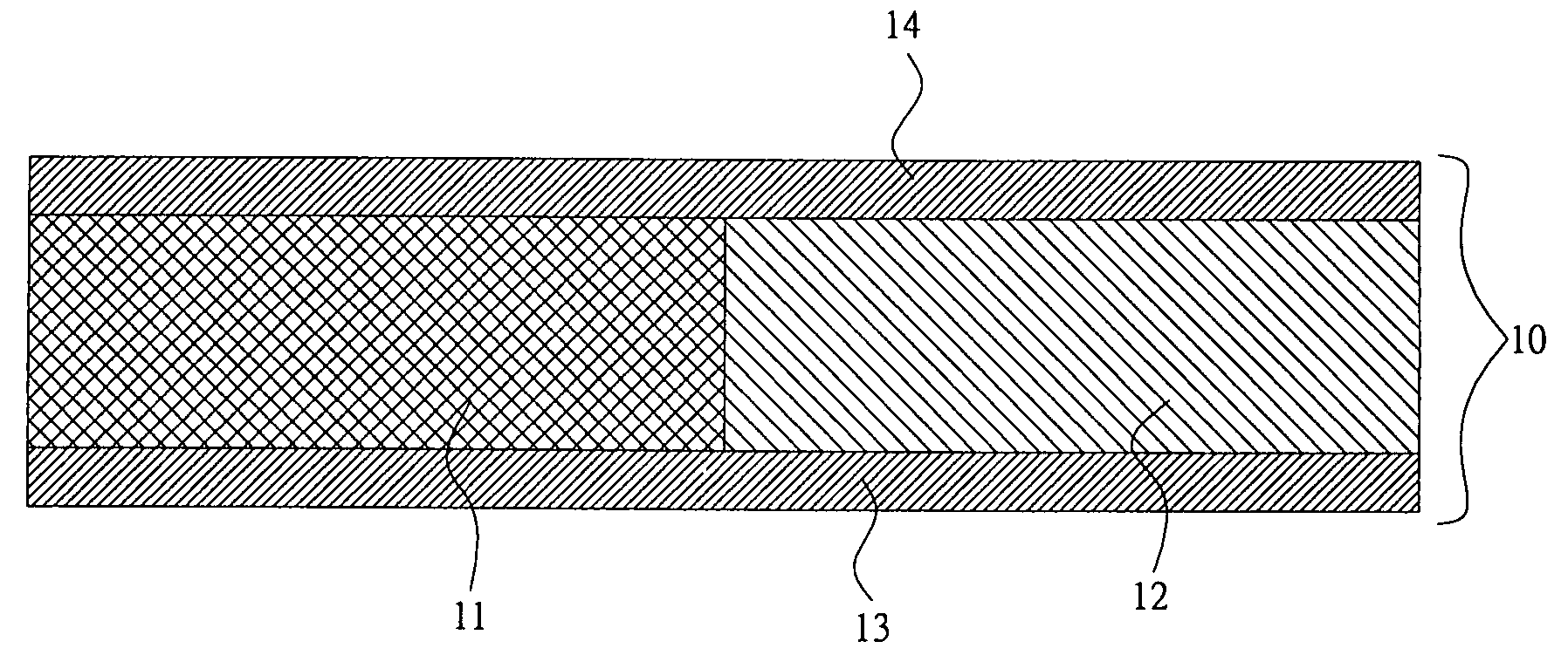
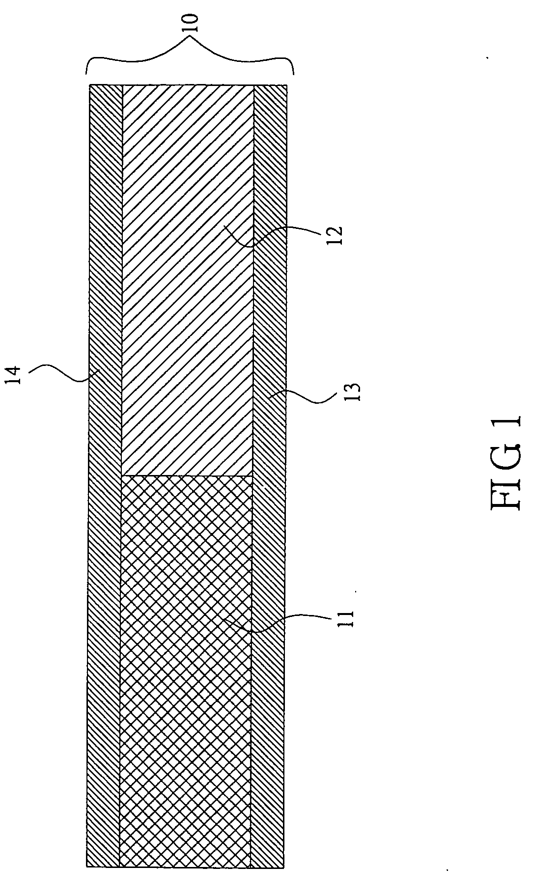
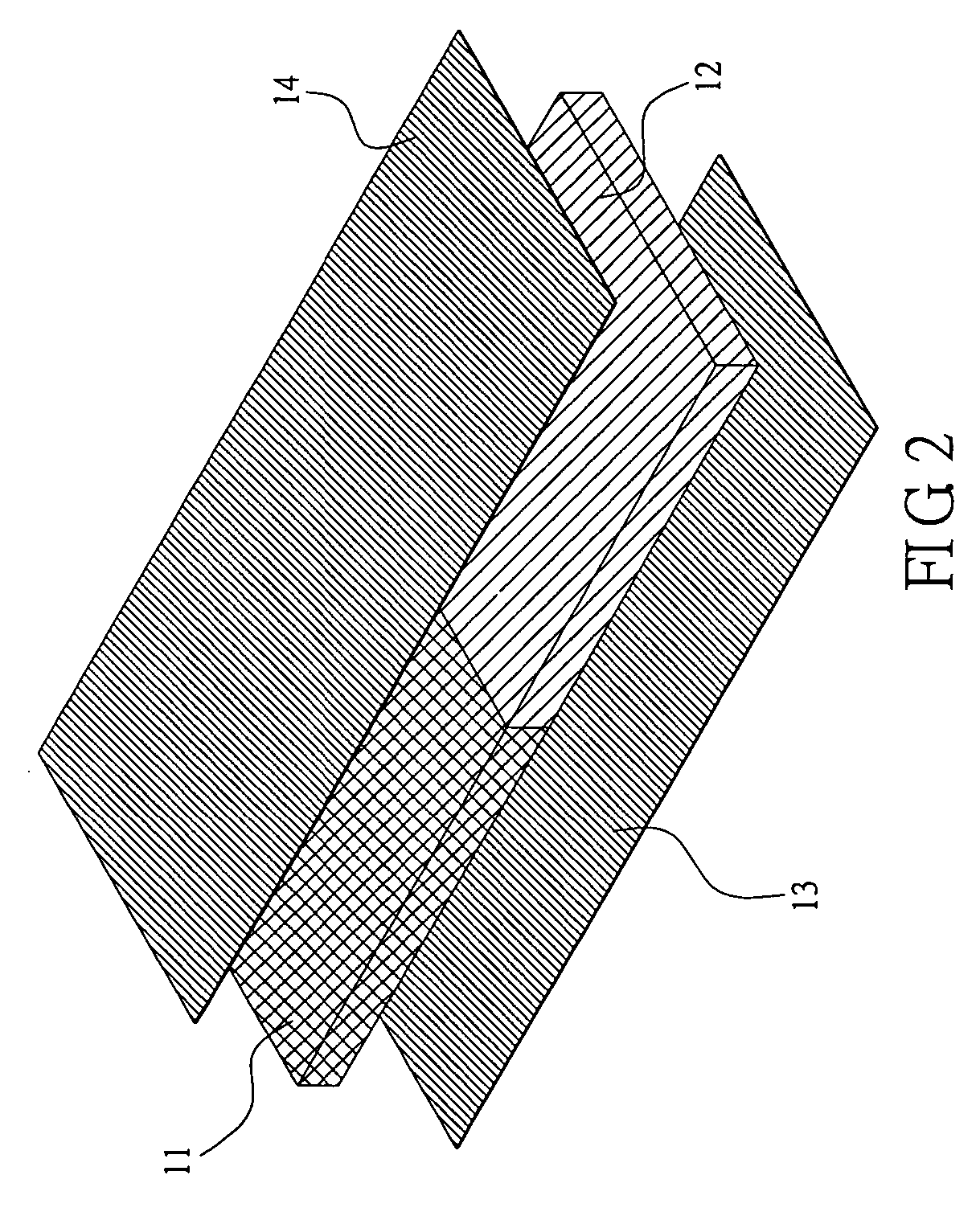
[0009] To improve the prior art and to satisfy the requirements of a high-frequency, high-speed and high-density electronic system, the invention provides a single-layered or multi-layered capacitor substrate imbedded with interleaving striped capacitors. The disclosed single-layered interleaving striped capacitor substrate uses several lines of dielectric materials with different dielectric coefficients (the relative dielectric coefficient εr) on one plane. A single piece of the capacitor substrate thus made can simultaneously provide the low dielectric coefficient (εr≦4) required for high-speed signal transmissions and the high dielectric coefficient (εr≧10) required by the decoupling capacitor that suppresses high-frequency noise. This helps increase the integrity of elements and the circuit density.
[0010] Furthermore, because the invention uses organic-ceramic hybrid materials as dielectric materials for the interleaving striped capacitor substrate, more than one layer of the disclosed striped capacitor substrate can be easily stacked on a multilayer print circuit board. And a multilayer striped capacitor substrate has the advantage of providing a 3D connection of high K stripes and a 3D connection of low K stripes such that the substrate's capacitance can further increase according to requirements.
[0012] Accordingly, the multilayer striped capacitor substrate (6˜20 layers) can provide very high capacitances (>100000 pf) to satisfy the needs of a high-speed digital system and motherboard to suppress high frequency noise.

Problems solved by technology

Its drawbacks are that the low dielectric coefficient material is not good at suppressing high-frequency noise and the integrity of passive elements on the print circuit board is poor.
It is not ideal for modern electronic systems where high frequency, high speed and compactness are the basic requirements.
The drawback of this method is that a single-layered capacitor substrate has only one dielectric coefficient that cannot simultaneously provide the capacitance properties required by a high-frequency and high-speed electronic system.
In order to satisfy different electronic requirements, the cost of the print circuit board inevitably increases due to stacking multiple layers of capacitor substrates.
For the mixed high-frequency analog and high-speed digital systems, the integrity of the added passive elements is still inadequate.
However, according to the ceramic material used, it is difficult to manufacture a multi layered capacitor substrate and apply it to a large size substrate, so the highest capacitance that can be obtained is limited and the applications are restricted.
Therefore the cost is high.

Method used


Image

  • Structure of an interleaving striped capacitor substrate
  • Structure of an interleaving striped capacitor substrate
  • Structure of an interleaving striped capacitor substrate

Examples


Embodiment Construction

[0024] The disclosed structure of an interleaving striped capacitor substrate utilizes several lines of dielectric materials of different dielectric coefficients (the relative dielectric coefficient εr) to make a striped capacitor substrate. Therefore, the single-layered capacitor substrate can simultaneously provide the low dielectric coefficient required for high-speed signal transmissions and the high dielectric coefficient required for the decoupling capacitor that suppresses high-frequency noise. Not only can the invention increase the transmission rate and suppress interference of high-frequency noise in an integrated electronic system, it can further reduce the number of layers on a substrate.

[0025] For different application ranges and for the capacitor substrate to be combined onto various circuit designs of print circuits, the invention provides two types of capacitor substrate structures. One contains a dielectric layer comprised of several lines of interleaving striped d...


PUM


Abstract

An interleaving striped capacitor substrate structure for pressing-type print circuit boards is disclosed. To meet the high-frequency, high-speed, and high-density requirements in modern electronic systems, the interleaving striped capacitor substrate structure uses several dielectric materials of different dielectric coefficients to make a dielectric layer. One dielectric layer can be stacked on another to form a multi-layered capacitor substrate so that a single capacitor substrate can provide the highest capacitance required for the decoupling capacitor to suppress high-frequency noise signals, and the lower dielectric coefficient substrate required for high-speed signal transmission. This simultaneously achieves the effects of reducing high-frequency transmission time and suppressing high-frequency noise.

Description

BACKGROUND OF THE INVENTION [0001] 1. Field of Invention [0002] The invention relates to a capacitor substrate and, in particular, to the structure of an interleaving striped capacitor substrate. [0003] 2. Related Art [0004] The print circuit board for supporting electronic elements in normal electronic systems is usually a planar substrate of a single low dielectric coefficient material (such as glass fiber cloths). Its drawbacks are that the low dielectric coefficient material is not good at suppressing high-frequency noise and the integrity of passive elements on the print circuit board is poor. It is not ideal for modern electronic systems where high frequency, high speed and compactness are the basic requirements. Consequently, the print circuit board needs to be improved to suppress high-frequency noise, to enhance the integration of elements, and to reduce high-speed signal delays. [0005] U.S. Pat. No. 5,161,086 provides an improved print circuit board to suppress high-freque...

Claims


Application Information

Patent Timeline
IPC IPC(8): H01G4/20H01G4/35H05K1/16
CPCH01G4/20H01G4/35H05K2201/0355H05K2201/0187H05K2201/0195H05K1/162
Inventor LEE, MIN-LINSHYU, CHIN-SUNLIU, SHUR-FENPAN, JING-PINKING, JINN-SHING
Owner IND TECH RES INST
Learn More