Deposition sources in general perform some of the required functions, but do not allow for the high volume production compatibility of immediately removable and replaceable deposition crucibles with self contained functions such as chemical containment, large area configuration, feedback and active
emission flux profile shaping.
Three dimensional, curved or any other non-planar substrates have not been used due to the difficulty of producing the required
emission flux patterns.
The uniform portion of the emission plume is inadequate for most industrial uses.
Excessive heat will degrade the
molecular chemistry and decompose the chemicals to an undesirable form.
The remaining fraction of
emission flux, deposited upon other components within the vacuum system may degrade the quality of the film on the substrate.
The condensed materials may fall back into the
crucible's heated interior, spit onto the substrate, or otherwise adversely affect the deposited film.
The difficulty to control the
exposure of the sensitive chemistries to high temperature surfaces of traditional deposition source structures leads to
chemical decomposition.
These sources do not exhibit extended flux uniformity along any axis.
If the organic-based films are not often maintained at a 95 percent or higher level of uniformity, fabricated devices may not operate properly.
Increasing the deposition source volatilization rate is an inefficient means to compensate for the reduced
deposition rate associated with separation distances in large area molecular deposition production systems.
Such output characteristics
restrict the ability of the source to successfully deposit functional organic or low temperature films upon substrates at sizes generally greater than 30 centimeters.
Low material utilization efficiency and deposition rates fail to address requirements for long term production applications.
Another problem associated with prior art open
crucible designs is that the emission profile is not constant over the life of the contained deposition
chemistry.
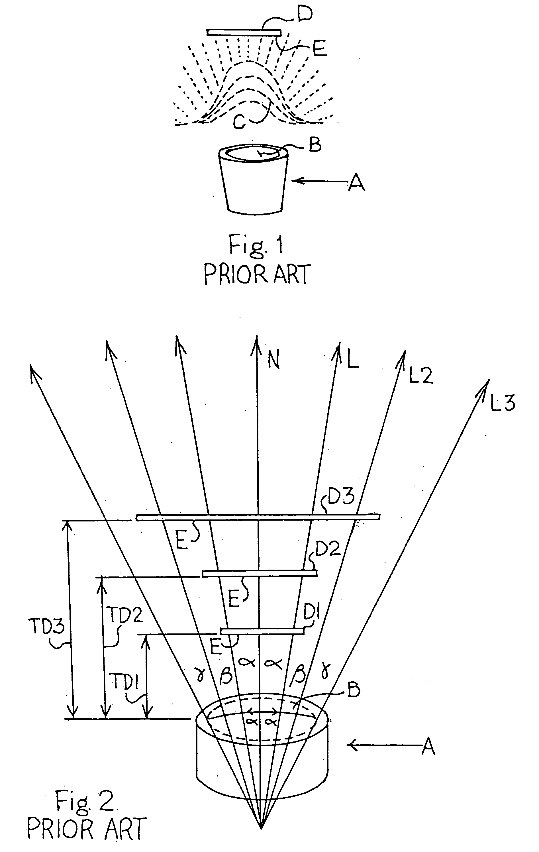
This change in the
line of sight from the
chemistry level in the deposition
crucible to substrates further tightens the emission profile and may reduce the coating uniformity upon the substrate as production coating proceeds.
By comparison, a 60
centimeter square substrate would require a proportional 120
centimeter separation distance which is generally impractical for vacuum systems size, performance, and cost.
Vacuum chambers must be made larger to accommodate the increased separation distances, requiring more powerful and more costly vacuum pumps.
Typical point-style sources for organic, or low temperature, materials as applied to larger substrates greater than approximately 30 centimeters exhibit increasingly unacceptable material utilization efficiencies.
Many organic
light emitting diode (
OLED) display chemistries cost thousands of dollars per
gram and effect competitive pricing of completed devices.
There is a substantial waste of expensive chemicals, since an increase in separation distance decreases material utilization efficiency from the deposition source crucible.
Cleaning is expensive because some chemicals, such as those used to produce organic displays are toxic as well as expensive.
Costs are further exaggerated because point or modified
point source crucibles generally contain approximately 10 to 100 cubic centimeters of
OLED chemistry, as limitations related to chemistry residency time and thermally induced degradation of many
molecular materials occurs.
Deposition technology in the prior art does not address the film quality as a function of
deposition rate.
At lower effective deposition rates, the background
contamination level of a vacuum processing system as measured by its
vacuum pressure level is at a higher relative level, which further contaminates the depositing film.
This is detrimental to the performance of traditional organic LED devices.
Prior art deposition source and crucible designs do not provide for ability to deliver increased effective
deposition rate to the substrate with increasing substrate size due to the limiting properties of critical organic materials, such as aluminum trishydroquinoline (AlQ3).
The prior art deposition source or crucible technology may produce inferior films and device performance upon the large substrates associated with large-scale production operations.
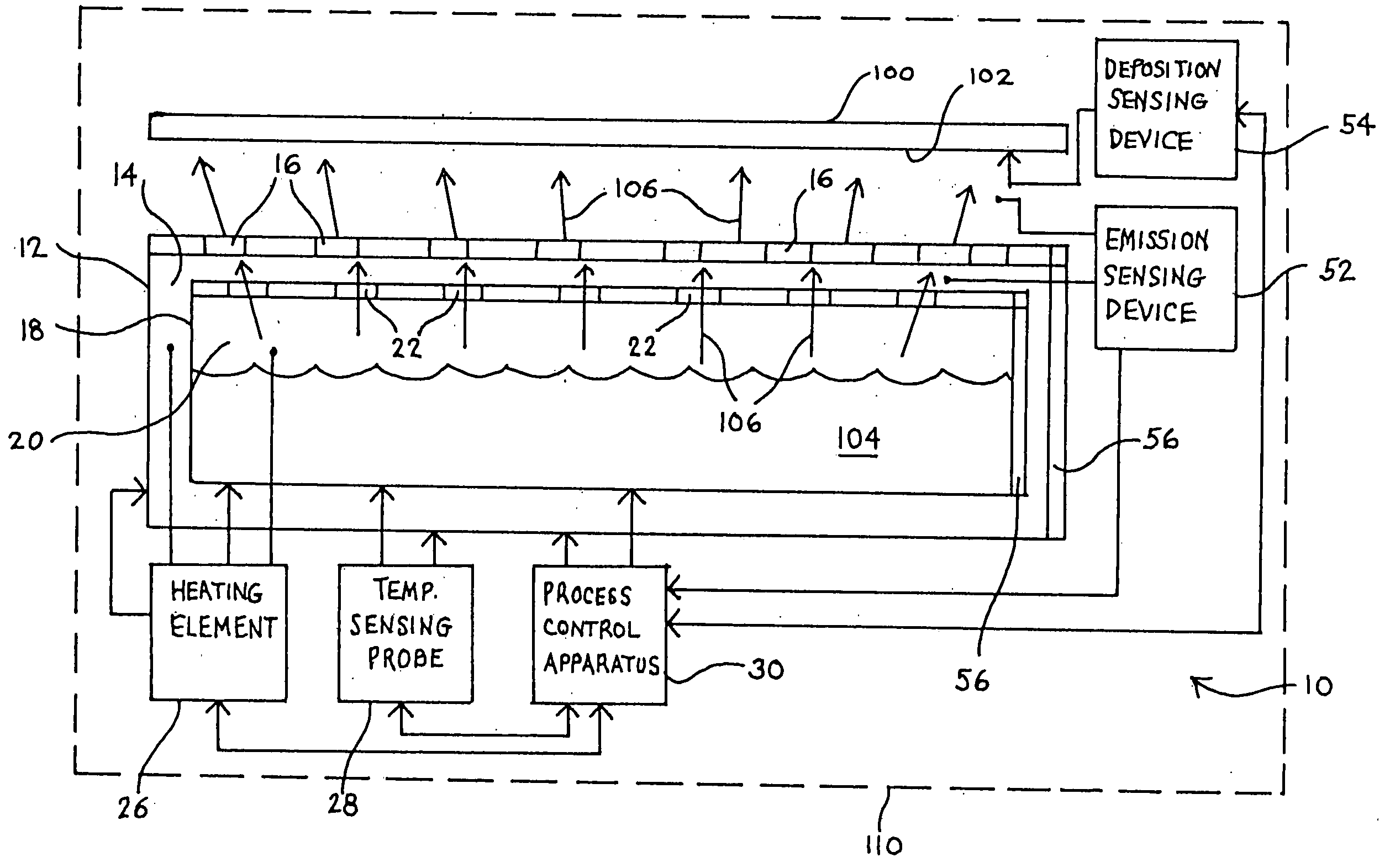
Further, the prior art does not indicate
linear configuration deposition sources or crucibles for either molecular or low temperature volatilizing materials with ability to provide a user desired and active tunable emission profile, precision
rate control, and enhanced film quality to large area substrates.
Due to the inability of previous prior art deposition sources or crucibles to actively profile the emission output, the material utilization efficiencies of these crucibles have been less than 50%.
Prior art point-style and
linear configuration deposition sources for metals evaporations do not provide for features such as an easily removable materials containing crucible from the deposition
source structure, or from the heater.
This has made it difficult to provide for a
linear configuration deposition source with a separate and readily removable crucible subassembly apart from an outer structure of the deposition source.
Prior art deposition source and crucible design does not provide for a linear configuration crucible
assembly, particularly for organic materials depositions, which is readily separable from the outer structure of the deposition source.
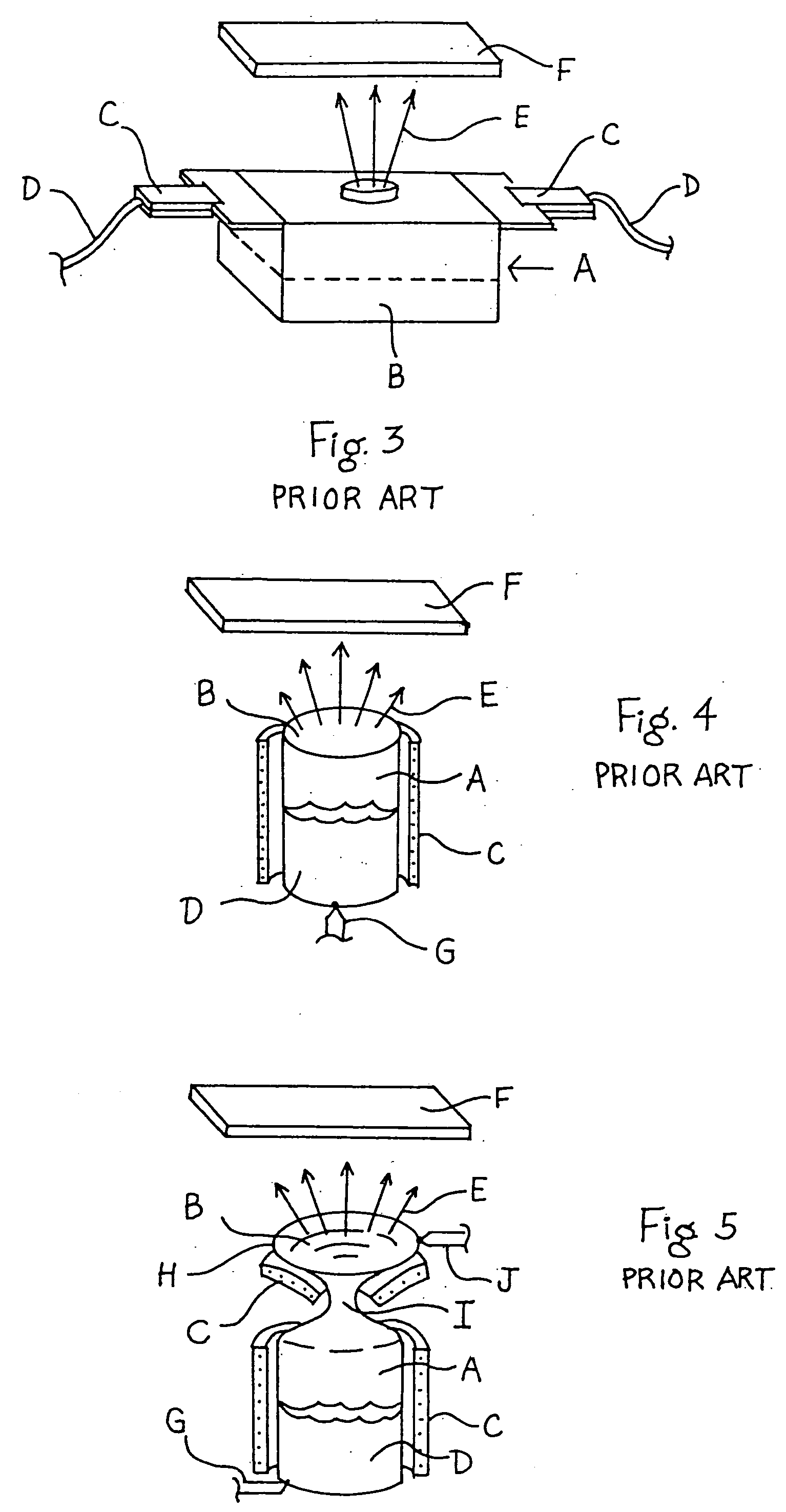
Also, prior art deposition crucibles are either simple open containers placed into a heated zone, or they are integrated with the deposition
source structure for requirements of heating and do not retain identity as a separate or removable subassembly with respect to the deposition
source structure.
Prior art does not provide for a crucible design within a deposition source structure that is easily rotatable with respect to either the deposition source structure or the substrate.
The prior art does not evidence linear or point-style deposition crucibles or sources with adjustability with respect to either of the deposition source structure or the target substrate.
Also, the prior art does not indicate that the coating uniformity of organic materials to a substrate may be tailored to a process at a particular range of deposition rate.
Prior art passive emission profile control only serves to degrade the material utilization efficiency of the deposition source.
The increased rate of deposition to the substrate when the substrate is positioned at the D1 position is also associated with poorer coating uniformity as the crucible emits a cosine-shaped flux.
Accordingly, such a crucible design does not have the ability to actively control the profile of the deposition chemistry emission and is subject to source to substrate separation distance requirements as the only method to control the deposited thin film uniformity to the substrate.

