
Method and a system for detecting and optinally isolating a rare event particle

a rare event particle and rare event technology, applied in the field of rare event particle detection and optional collection, can solve the problems of low signal/noise ratio, reference does not address, and the time used for detection of signal from a particle in the sample liquid is extremely short, so as to achieve the effect of increasing the signal to noise ratio and substantially increasing the time used for detection of signal

Inactive Publication Date: 2005-07-07
CHEMOMETEC AS
View PDF9 Cites 76 Cited by
  • Summary
  • Abstract
  • Description
  • Claims
  • Application Information

AI Technical Summary

Benefits of technology

[0024] By serial or parallel analysis of a number of volumes of sample each comprising at least 0.1 μl, a substantially large volume of liquid sample may be analysed in a very simple manner. In contrast to flow cytometry, the steps of arranging the sample and detecting the signals is separated in two steps. Thereby the time used for detection of signal from a particle in the sample liquid can be increased and the signal to noise ratio be increased substantially.
[0035] According to this aspect of the invention, it is possible to isolate a rare event particle from other non-rare particles present in the sample using serial dilution of the sub-volume containing the rare event particle.

Problems solved by technology

From this it follows that the time for accumulation of electromagnetic radiation from any one particle during its stay in the detection area is extremely short.
This results in a low signal / noise ratio.
The reference does not address the problem of identifying rare particles in the absence of other particles.
This method cannot be used when the size and / or shape of the rare cell is not known.
The method is exclusively adapted for used with urine samples and suffers from the disadvantage that the detected rare event particle cannot be isolated and analysed further, since it is absorbed on a surface.
This method thus requires expensive equipment.
Such instruments can only be operated accurately by trained personnel, since a number of choices have to be made by the operator and these choices in turn affect the accuracy of the assessment.

Method used


Image

  • Method and a system for detecting and optinally isolating a rare event particle
  • Method and a system for detecting and optinally isolating a rare event particle
  • Method and a system for detecting and optinally isolating a rare event particle

Examples


example 1a

A System Suitable for the Detection and Assessment of Rare Particles

[0303] A system suited for the detection and assessment of rare particles, based on the interaction of electromagnetic radiation with the particles, such as absorption or fluorescence is illustrated schematically in FIG. 9.

[0304] The figure illustrates a system, where the sample 901 is added to a sampling compartment and mixed with reagent 903, preferably where the volume of the reagent is controlled with a pump 904 capable of substantially precisely measuring a predetermined volume of the reagent.

[0305] After mixing the sample / reagent mixture is transported into the detection unit 907 by the use of a pump 909. The counting unit is illustrated schematically in FIG. 8.

[0306]FIG. 8 illustrates many of the important units and / or operations of a detection unit 801. Most of the controlling of the counting unit, and preferably means to perform analysis of the spatial image are located in the main control unit 802. The...

example 1b

System for the Detection and Assessment of Rare Particles

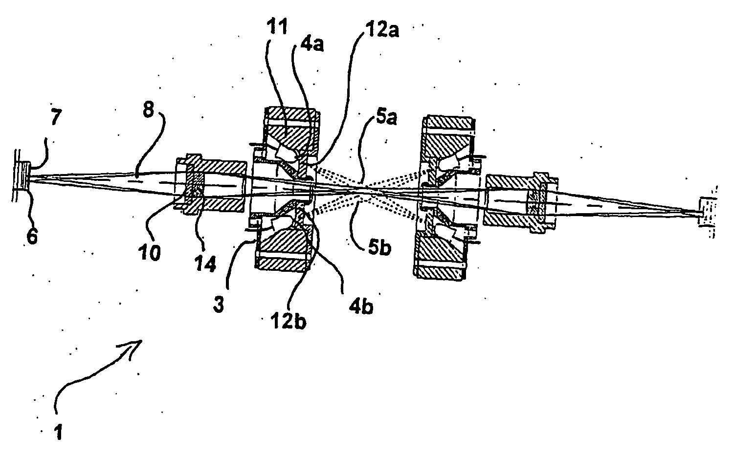
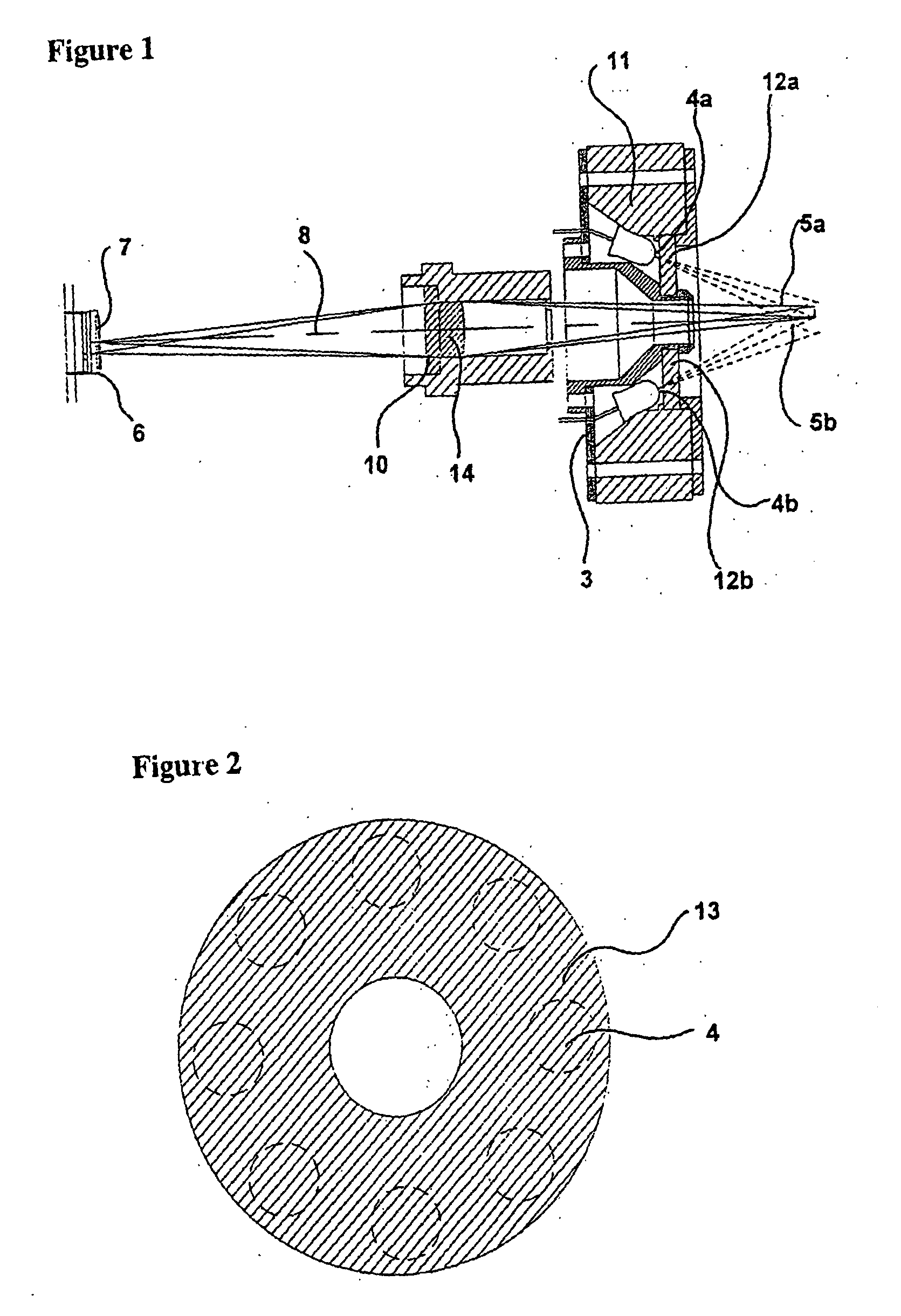
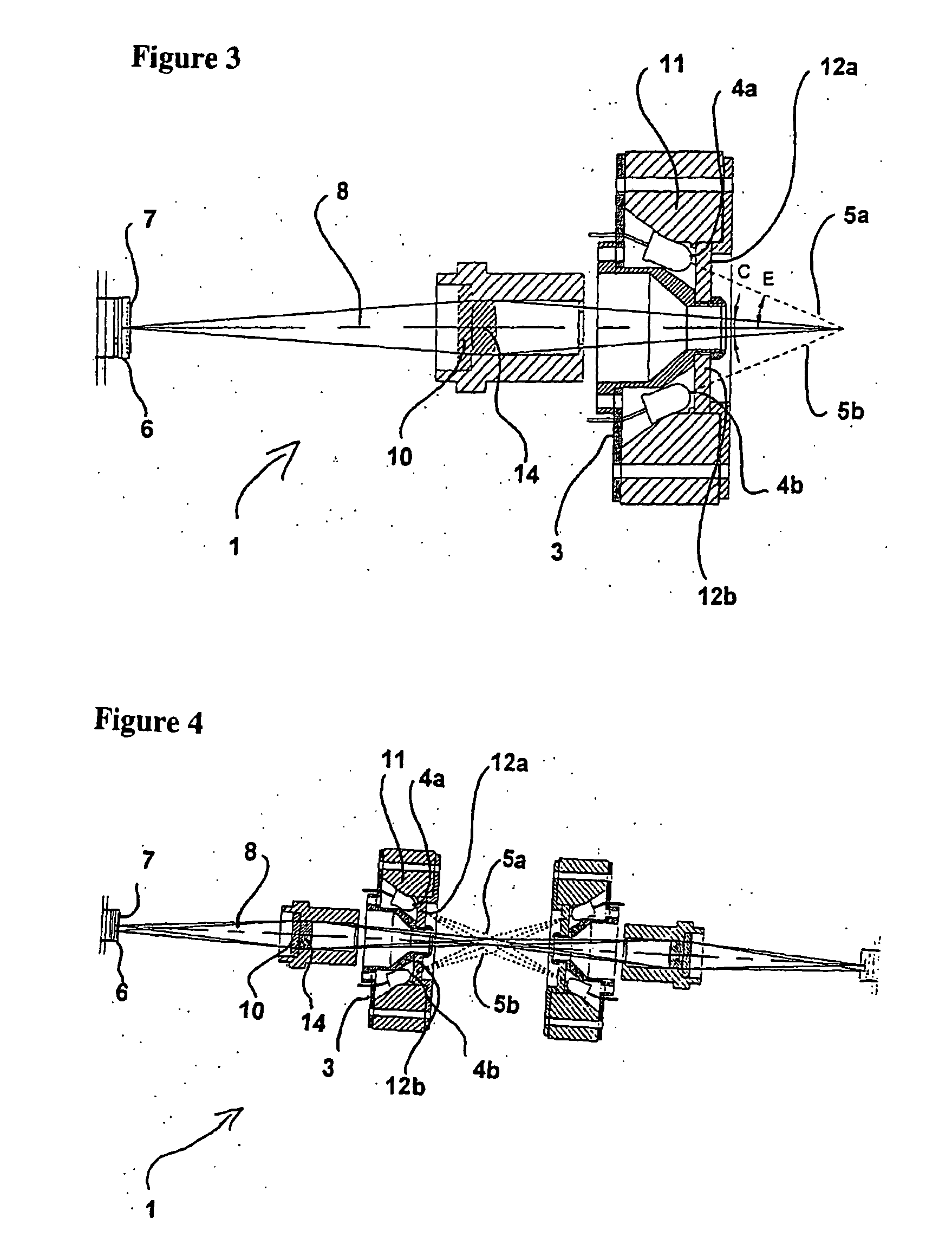
[0311]FIG. 14 illustrates a suitable optical system for performing such analyses within the detection unit 907. 1401 is a CCD that captures the image. 1402 is an achromatic glass lenses used for imaging the volume inside the sample compartment to the CCD. The position of the lenses along the optical axis determines the transversal magnification and is used for focusing the system. 1403 is an aperture. 1404 is a glass emission absorbance filter, allowing substantially only red fluorescent light to pass. 1405 is the sample compartment being in close proximity to the optical system object plane. 1406 is the glass excitation interference and absorbance filter, allowing substantially only green excitation light to pass. 1407 is the Light Emitting Diodes (LED) working as a light source in the optical system emitting green light at the wavelength of around 530 nm.

[0312] The volume of sample for each measurement is approximately 3 μ...

example 2

Comparison of the Performance of a System According to the Present Invention and a Commercially Available System

[0318] 10 samples of leukodepleted Red Blood cell units (SAGM blood units), prepared from human blood were analysed with a method according to the present invention and the results compared to a commercially available method suitable for the analysis.

[0319] For the measurement by a method according to the present invention a volume of 300 μl of the sample was added to 150 μl reagent. The reagent consisted of Propidium iodide (25 μg / ml), Triton X-100 (1.5% w / w) and polymer surfactants Pluronic (1.0% w / w) dissolved in water. The sample reagent solution was mixed by pipetting prior to analysing in the detection unit. A total of 20 images were analysed and the number of observed rare particles were thus counted in a volume corresponding to approximately 20 μl of the initial sample. This analysis were carried out twice rendering duplicate results for each sample with the syst...


PUM


Abstract

The invention relates to the field of detecting and optionally collecting and isolating rare event particles. The method according to the invention is based on relatively simple optical equipment, which requires a few and uncomplicated decisions for the user of the system. The method is based on the acquisition of an image of relatively low resolution and magnification of a large volume of sample and detecting the presence or absence of the rare event particle. The method is then repeated with at least one further volume of sample. The method is particularly adapted for detection of white blood cells in leuko-depleted blood.

Description

TECHNICAL FIELD [0001] This application is a non-provisional claiming priority from Danish patent application No. PA 2001 01346 filed 16 Sep. 2001, which is hereby incorporated by reference in its entirety. All patent and non-patent references cited in that application, or in the present application, are also hereby incorporated by reference in their entirety. [0002] The invention relates to the field of detecting and optionally collecting and isolating rare event particles. PRIOR ART [0003] Methods and systems for the detection of rare event particles are known from the prior art. Most of these methods are based on analysis of samples containing rare event particles in flow cytometers or cell analysers. In a flow cytometer, the sample liquid is moved by a carrier stream at high speed through a detection area, where the particles normally are illuminated and electromagnetic radiation from the particles are detected by e.g. a CCD. The sample liquid is preferably so thin that only or ...

Claims


Application Information

Patent Timeline
IPC IPC(8): G01N15/02G01N15/14G01N33/52G01N33/569
CPCG01N15/02G01N15/14G01N33/56972G01N33/56911G01N33/56966G01N33/52
Inventor LARSEN, RASMUS DINES
Owner CHEMOMETEC AS
Features
  • Generate Ideas
  • Intellectual Property
  • Life Sciences
  • Materials
  • Tech Scout
  • Unparalleled Data Quality
  • Higher Quality Content
  • 60% Fewer Hallucinations
Learn More