High Q linear controlled variable capacitor using translinear amplifier

Inactive Publication Date: 2005-07-14
DIALOG SEMICONDUCTOR
View PDF10 Cites 27 Cited by
  • Summary
  • Abstract
  • Description
  • Claims
  • Application Information

AI Technical Summary

Benefits of technology

[0030] Even more, with a translinear amplifier with a gain different from 1, the whole concept gains one more de

Problems solved by technology

However the characteristics are non-linear and are widely temperature and process dependent.
There is also a significant leakage current problem.
In addition the switching of the individual capacitors causes swit

Method used


Image

  • High Q linear controlled variable capacitor using translinear amplifier
  • High Q linear controlled variable capacitor using translinear amplifier
  • High Q linear controlled variable capacitor using translinear amplifier

Examples


Embodiment Construction

[0048] The objectives of this invention are to control the capacitance of a variable capacitor in a strictly linear mode through a tuning voltage. A fundamental requirement is to achieve a high Q-factor at the same time.

[0049] A discussion of the general principles of a voltage controlled variable capacitor with linear characteristic, formed of a larger number of fixed capacitor segments and a corresponding number of switching elements, using operational amplifiers is disclosed in the related patent application DS03-005A, the entire contents of which is incorporated herewith by reference.

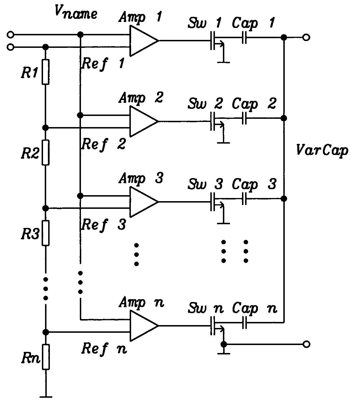
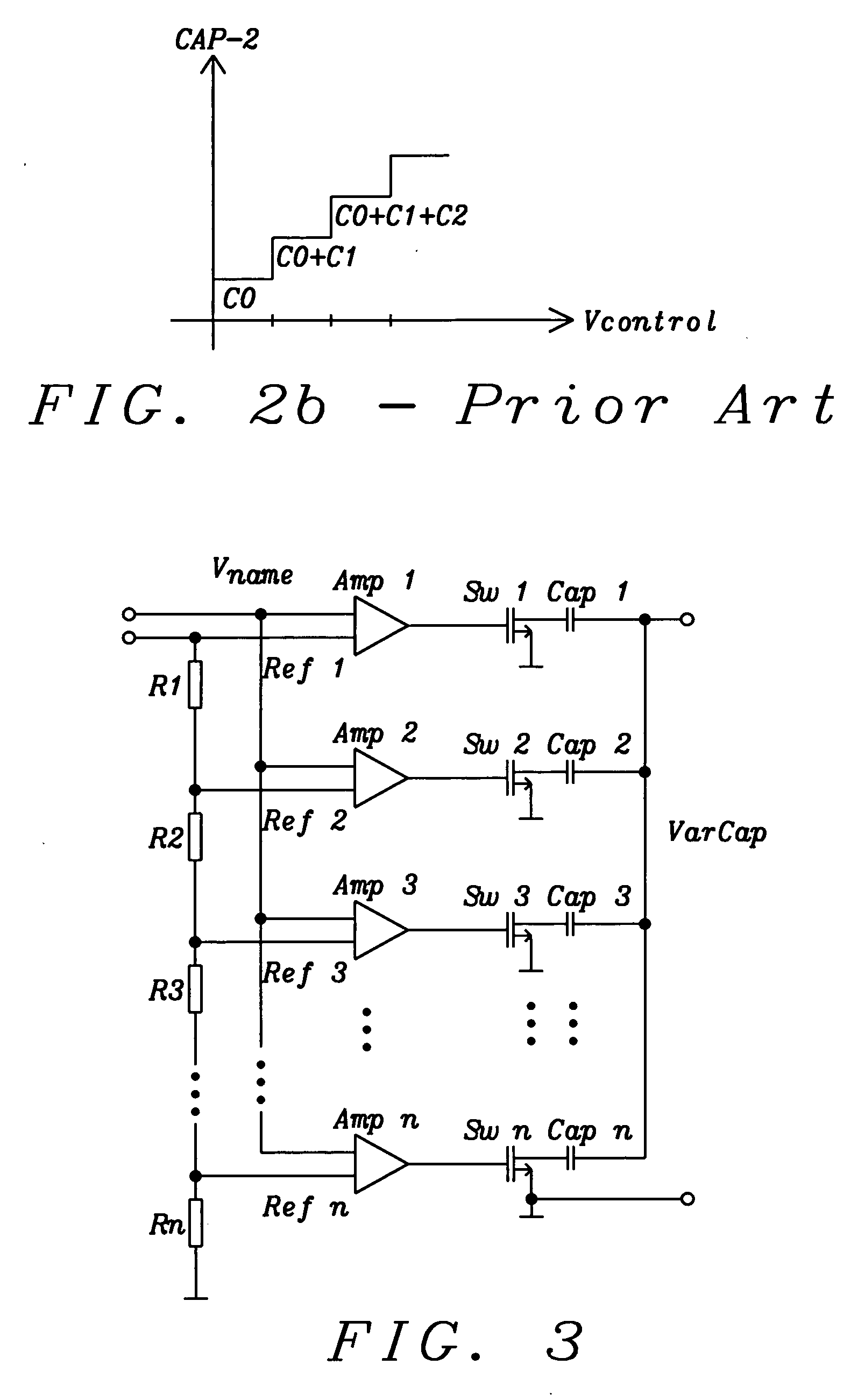
[0050]FIG. 3 shows a principal circuit diagram of the referenced related patent application. Amp 1 to Amp n are said operational amplifiers, Sw 1 to Sw n are the switching devices and Cap 1 to Cap n are said capacitors that will be switched in parallel. As an example, a resistor chain R1 to Rn, or a similar circuit, produces a series of voltage references Ref 1 to Ref n and each of said operationa...


PUM


Abstract

A voltage controlled variable capacitor, formed of a larger number of fixed capacitor segments and a corresponding number of switching elements, uses translinear amplifiers to control each switching element. Each translinear amplifier linearly switches from the fully off to the fully on state; a minimum number of switching stages (ideally only one) is in the mode-of-change at any one time with a minimum overlap. The arrangement achieves a nearly linear change of capacitance at linear tuning voltage change, while resulting in high Q-factor due to the low RDSon and high RDSoff of the fully switched stages. The invention eliminates temperature and voltage dependencies of other solutions like varactor diodes.

Description

BACKGROUND OF THE INVENTION [0001] (1) Field of the Invention [0002] The invention relates to a voltage controlled variable capacitor, and more particularly, to a variable capacitor, formed of a larger number of fixed capacitor segments and a corresponding number of switching elements, which are typically integrated with the capacitance controlling functions on an integrated semiconductor circuit. [0003] (2) Description of Prior Art [0004] One example of a voltage-controlled capacitor is a varactor diode. When a reverse voltage is applied to a PN junction, it creates a depletion region, essentially devoid of carriers, which behaves as the dielectric of a capacitor. The depletion region increases as reverse voltage across it increases; thus the junction capacitance will decrease as the voltage across the PN junction increases. However the characteristics are non-linear and are widely temperature and process dependent. There is also a significant leakage current problem. Varactor diod...

Claims


Application Information

Patent Timeline
IPC IPC(8): H03H11/12
CPCH03H11/1291
Inventor SIBRAI, ANDREASNIEDERL, JOSEF
Owner DIALOG SEMICONDUCTOR
Why Eureka
Try Eureka