Method and apparatus for releasing metal-resin joint

a metal-resin joint and metal-resin technology, applied in the direction of apparatus for removing/armouring cables, crystal growth processes, electric cable installations, etc., can solve the problems of increasing materials' requirements in strength, function, safety, cost, and inability to separate the two parts by mechanical methods, and achieves small energy consumption and low cost. , the effect of easy and convenien

Inactive Publication Date: 2005-07-21
PANASONIC CORP
View PDF11 Cites 1 Cited by
  • Summary
  • Abstract
  • Description
  • Claims
  • Application Information

AI Technical Summary

Benefits of technology

[0013] In the disposal / recycling of an article comprising a metal-resin joint, an object of the present invention is to provide an inexpensive and easy method and apparatus for separating the resin portion from the metal portion with small energy consumption and without destroying at least the metal portion.

Problems solved by technology

With the recent progress of technological development, there are increasingly strict and complicated requirements for materials in terms of strength, function, safety, cost, etc.
However, if the metal portion and the resin portion are firmly bonded, it is basically impossible to separate the two portions by a mechanical method.
This method, however, requires a large amount of energy and presents a problem of carbon dioxide and dioxin emissions.
However, this method requires high cost for separation because of the necessity to use liquid nitrogen or the like and, in addition, is not capable of completely separating the resin from the metal in principle.
It is difficult, however, to completely separate resin from metal by shredding using a shredder.
However, this method requires a large amount of energy for heating and pressurization and involves destruction of the metal portion, although the separation of the resin from the metal is possible.
However, this method separates the resin film from the steel plate by maintaining the steel plate at such a potential that the plated layer such as zinc is selectively dissolved, so the method is applicable only to limited metals such as the zinc-plated steel plate and therefore lacks versatility.
However, although this method is effective when the resin portion of a composite material is phenol resin that easily swells with alkaline solution, it is not suitable for other composite materials.
As described above, each of these conventional methods of separating a metal-resin joint has its own drawbacks and generally involves destruction of the article comprising a metal-resin joint.

Method used


Image

  • Method and apparatus for releasing metal-resin joint
  • Method and apparatus for releasing metal-resin joint
  • Method and apparatus for releasing metal-resin joint

Examples


example 1

(i) Preparation of Sample 1

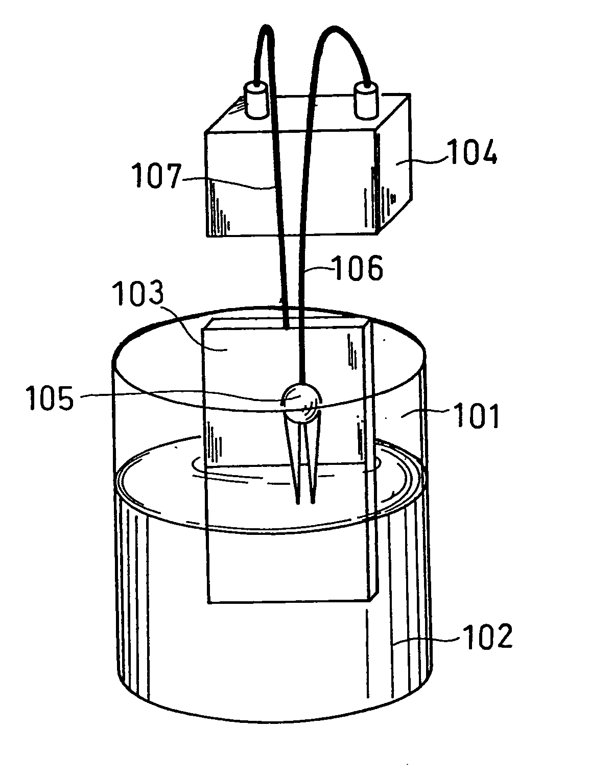
[0073] A steel plate of 0.10 mm in thickness, 50 mm in length and 30 mm in width was prepared. An adhesive comprising a synthetic rubber dissolved in a solvent (quick-curing bond G17 manufactured by Konishi Co., Ltd.) was applied onto one side of this steel plate, and an acrylic plate of polymethyl methacrylate of 50 mm in length, 30 mm in width and 2 mm in thickness was placed thereon so as to cover the steel plate. In this way, five same samples 1a, 1b, . . . 1e having a joint of a steel plate and an acrylic plate were obtained.

(ii) Fabrication of Separating Apparatus

[0074] Five 100 ml beakers made of tetrafluoroethylene were prepared, and an aqueous solution of sodium hydroxide (25° C.) of 0.01 M, 0.1 M, 3 M, 7 M or 15 M was introduced in an amount of 100 ml into each of the beakers. These beakers are named 2a, 2b, 2c, 2d and 2e. Into each beaker were immersed a nickel plate (50 mm long, 30 mm wide and 0.5 mm thick) serving as a counter electrode a...

example 2

[0084] Next, four apparatuses the same as the test apparatus of the sample 1d were produced. Then, by varying the value of the current passed between the sample and the counter electrode at room temperature, the change in time required to complete separation was examined. Table 2 shows the results together with the potentials of the metal portions of the samples relative to the standard hydrogen electrode.

TABLE 2Potential of metalportion relative toTime required toCurrent valuestandard hydrogencomplete separation(mA)electrode (V)(h)1−1.10610−1.234100−1.373.5500−1.613.5800−1.813.51000−1.943.5

[0085] At the current value of 1 mA, although it was barely possible to detect hydrogen generation on the surface of the metal portion of the sample immediately after the start of the test, separation of the acrylic plate from the steel plate was observed 6 hours after the start of the test. As the current value was increased to 10 mA and 100 mA, the time required to complete separation was sho...

example 3

[0087] Five apparatuses the same as the test apparatus of the sample 1d were produced. Then, by immersing each beaker in hot water baths of various temperatures, separation tests of the metal-resin joints of samples were performed in aqueous solutions of sodium hydroxide of various temperatures. The value of the current passed between the metal portion of the metal-resin joint and the counter electrode was 10 mA.

[0088] For three samples, the bath temperatures were set at 25° C., 45° C. and 65° C., respectively, and the same separation tests as that of Example 1 were performed.

[0089] For another sample, the beaker was immersed in water of 25° C. in an ultrasonic washing machine (40 kHz, output 200 W), and the same separation test as that of Example 1 was performed.

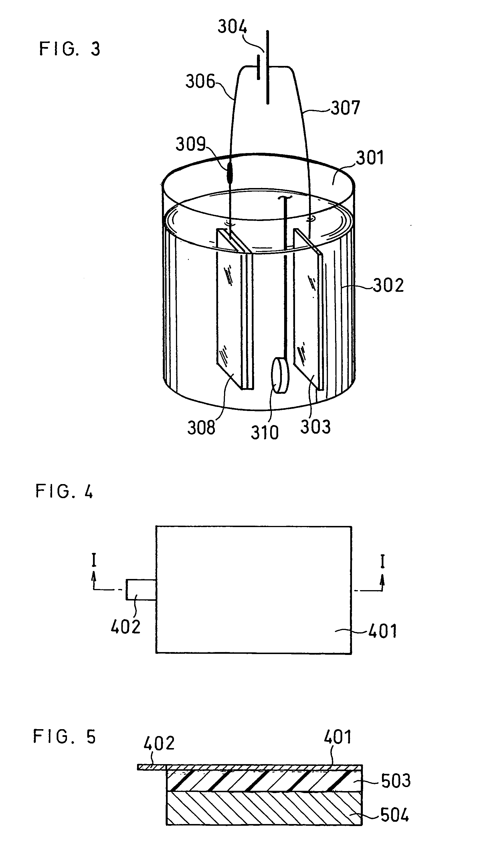
[0090] The remaining sample was processed as follows. FIG. 4 is a plane view thereof. Also, FIG. 5 is a cross-sectional view taken on line I-I of FIG. 4.

[0091] First, to a steel plate 401 of a sample was welded an ear p...


PUM

PropertyMeasurementUnit
voltageaaaaaaaaaa
voltageaaaaaaaaaa
temperatureaaaaaaaaaa

Abstract

A method for separating a metal-resin joint including the steps of: (1) immersing an article including a metal-resin joint with a counter electrode in an alkaline solution; and (2) applying a voltage over a certain time period between the metal portion of the joint and the counter electrode such that the potential of the metal portion is lower than that of a standard hydrogen electrode.

Description

TECHNICAL FIELD [0001] The present invention relates to a method and apparatus for separating the resin portion from the metal portion of a metal-resin joint of an article without physically damaging the article. BACKGROUND ART [0002] With the recent progress of technological development, there are increasingly strict and complicated requirements for materials in terms of strength, function, safety, cost, etc. Since materials consisting of one material can only meet such requirements in a limited manner, composite materials comprising two or more kinds of materials are being increasingly used. Among them, composite materials comprising a joint of metal and resin are in frequent use. Examples of these combined materials include: electric wires comprising metal wires covered with a resin film; circuit boards for use in electronic equipment comprising integrated metal and resin; and automobile / airplane parts comprising metal and metal, or metal and resin, which are bonded with an adhes...

Claims


Application Information

Patent Timeline
Patent Type & Authority Applications(United States)
IPC IPC(8): B29B17/02B29B17/04C08J11/06C25F1/00C25F1/02C25F5/00
CPCB29B17/02Y10T156/1158B29B2017/0293B29B2017/0296B29B2017/0436B29K2021/00B29K2027/06B29K2033/12B29K2069/00B29K2075/00B29K2077/00B29K2705/00B29K2705/02B29K2705/04B29K2705/06B29K2705/08B29K2705/10B29K2705/12B29L2009/003B29L2009/005B29L2031/3425B29L2031/707C25F1/00C25F5/00Y10T29/53274Y10T29/49755Y10T156/19B29B17/04Y02W30/62
Inventor NANNO, TETSUOIZUMI, YOICHI
Owner PANASONIC CORP
Why Eureka
Try Eureka