Current sensor

a current sensor and current transformer technology, applied in liquid/fluent solid measurement, instruments, machines/engines, etc., can solve the problems of measurement errors, difficult calibration or maintenance with this approach, and large weight of current transformers, etc., to achieve low weight, low cost, and low cost

Active Publication Date: 2005-07-21
THE UNITED STATES AS REPRESENTED BY THE DEPARTMENT OF ENERGY
View PDF37 Cites 235 Cited by
  • Summary
  • Abstract
  • Description
  • Claims
  • Application Information

AI Technical Summary

Benefits of technology

[0027] One advantage of the present invention is that it is very low in weight.
[0028] Another advantage of the present invention is that revenue accuracy measurements can be achieved for power system applications.
[0029] Another advantage of the present invention is that relaying accuracy measurements can be achieved for power system applications.
[0030] Another advantage of the p

Problems solved by technology

Furthermore, at high voltages found in power transmission systems, current transformers become extremely large and heavy and contain insulating mineral oil in order to satisfy the dielectric requirements of the application.
Calibration is difficult to achieve or maintain with this approach.
Stray magnetic fields generated by other currents located nearby will also cause measurement errors.
Optical current sensors are difficult to design as a clamp-on device, and they suffer from high costs.
Current sensors that rely on one or two point magnetic field sensors do not approach a good approximation of Ampere's law, and are therefore prone to inaccuracies due to the presence of external magnetic fields and the position of the conductor relative to the sensor(s).
This method requires the induction of a test current into the conductor being monitored, which may be difficult when high currents are being measured on a power line.
This method suffers from being sensitive to stray magnetic fields in the vicinity of the conductor under test, resulting in erroneous readings from the sensor pair.
This approach does not eliminate errors due to stray magnetic fields, and requires careful geometric stability of the sensor locations to maintain calibration.
Other than reducing the magnetic flux at the sensors, there is no clear advantage of this approach.
type. However, these methods suffer from measurement errors due to magnetic saturation of the core material, hysteresis effects in the core material, temperature dependent magnetic permeability of the core material, and non-linearity of the core mat
erial. In addition, the methods are only applicable to the measurement of AC cu
ic fields. This approach suffers from errors due to high permeability materials being present near the sensors, incomplete shielding from stray magnetic fields, and rigid geometric alignment required to maintain c
However, this approach does not address errors caused by stray magnetic fields, and it is generally difficult to seamlessly combine signals covering different frequency ranges.
However, the efficacy of the method is not disclosed, as no mention of Ampere's law is referred to when determining the positions of the sensors relative to the conductor, and the device is does not clamp on to the conductor.
The two concentric rings do not provide effective cancellation of errors due to stray magnetic fields,

Method used


Image

  • Current sensor
  • Current sensor
  • Current sensor

Examples


first embodiment

[0067] temperature compensation is shown in FIG. 3. The ambient temperature of the printed circuit board is detected by temperature sensor 309 and used to generate a voltage that is proportional to temperature, or a digital number that is proportional to temperature. The error voltage is generated in signal processor 310 using an analog amplifier, or it may be generated by a digital look-up table stored in an electronic memory that is addressed by a number representing the ambient temperature, and provides a digital number that is converted to an analog voltage using a conventional digital-to-analog converter. The error voltage controls a voltage regulator 301 that generates the power supply voltage for all of the magnetic field sensors. As the temperature of the printed wiring board varies, the sensitivity of the magnetic field sensors varies. For example, the output signal may vary by +3% over a temperature change of 100 degrees C. This is compensated by an equal and opposite vari...

third embodiment

[0069] In temperature compensation shown in FIGS. 5A and 5B, a magnetic field is generated in the vicinity of one or more of the magnetic field sensors. The magnetic field can be a DC field created by a permanent magnet 509 in close proximity to one magnetic field sensor 507, or a DC or AC field generated by an electromagnet such as a solenoid 503. The magnetic field sensor 507 should be selected to have a temperature dependence that is substantially the same as the average temperature dependence of the entire array of magnetic field sensors. If a DC magnetic field is used, then the current sensor can only be used to measure AC currents. If an AC magnetic field is used, then the current sensor can be used to measure DC and AC currents. The magnitude of the extra magnetic field in the region surrounding the magnetic field sensor is kept as stable as possible. For the permanent magnet 509, this is achieved by selecting the permanent magnet material to have thermally stable properties,...

fourth embodiment

[0070] In temperature compensation shown in FIGS. 6A, 6B and 6C, a separate magnetic field sensor 604 is placed inside of a stable solenoid coil 603 that is in turn driven by a constant current generator. The magnetic field generated by the solenoid coil 603 is an AC field. The solenoid coil 603 and the magnetic field sensor 604 are oriented in such a way that the direction of the generated and detected magnetic field is substantially perpendicular to the sensitivity axis of the magnetic field sensors 302 already present on the printed circuit board 606. The magnetic field sensor 604 should be selected to have a temperature dependence that is substantially the same as the average temperature dependence of the entire array of magnetic field sensors. The magnitude of the extra magnetic field in the region surrounding the magnetic field sensor 604 is kept as stable as possible. For the solenoid 603, a stable magnetic field is achieved by constructing the solenoid coil mandrel from stab...


PUM


Abstract

A current sensor is described that uses a plurality of magnetic field sensors positioned around a current carrying conductor. The sensor can be hinged to allow clamping to a conductor. The current sensor provides high measurement accuracy for both DC and AC currents, and is substantially immune to the effects of temperature, conductor position, nearby current carrying conductors and aging.

Description

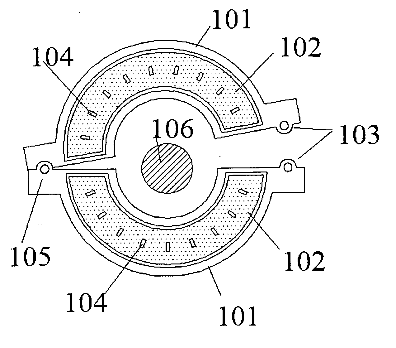
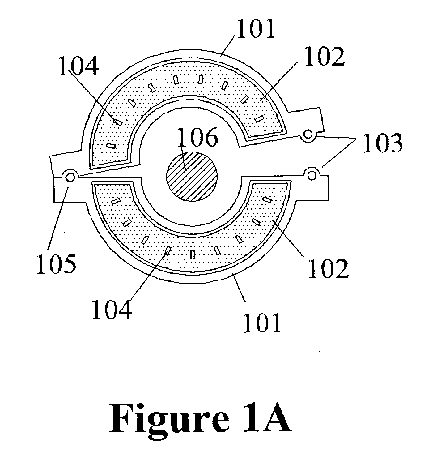
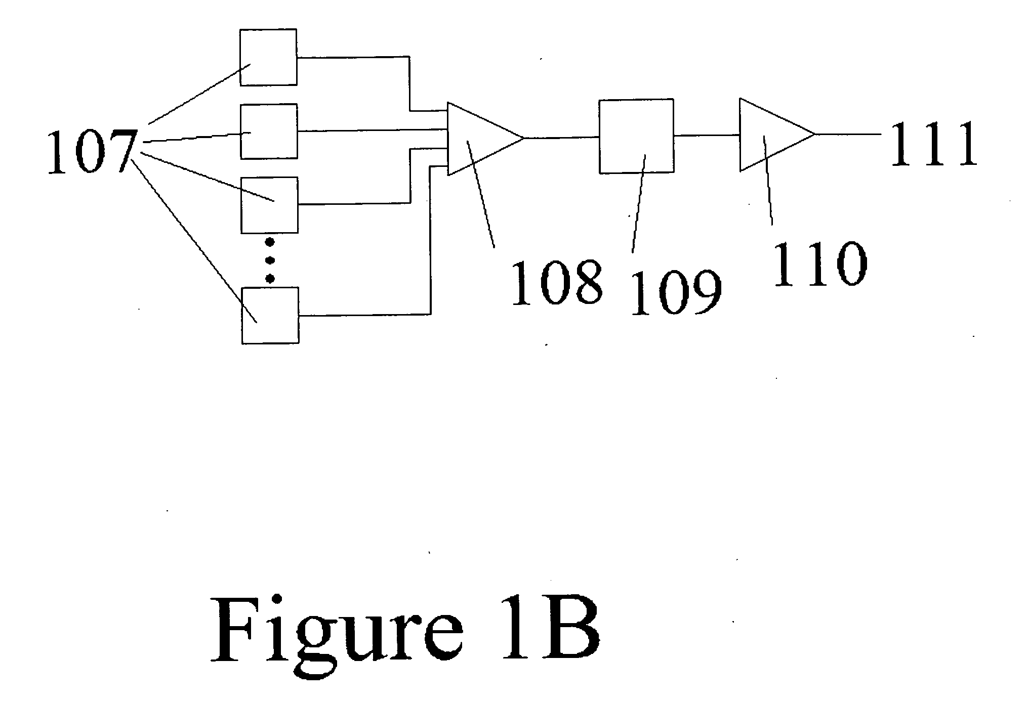
CROSS REFERENCE TO PRIOR APPLICATION [0001] This application claims the priority of U.S. Provisional Application Ser. No. 60 / 481,906 filed Jan. 16, 2004 and entitled “CURRENT SENSOR”, the subject matter of which is incorporated herein by reference.FEDERAL GOVERNMENT STATEMENT [0002] This invention was made with Government support under contract DE-FG03-01 ER83228 awarded by the Department of Energy. The Government has certain rights to this invention.FIELD OF THE INVENTION [0003] The present invention relates to a clamp-on current sensor for measuring alternating and direct electrical current such as the current of a high-voltage power transmission line or a substation bus conductor. DESCRIPTION OF THE PRIOR ART [0004] A variety of current measurement techniques are known in the art, including current transformers, Rogowski coil transformers, resistive shunts in series or in parallel with a current-carrying conductor, magnetic field point sensors, magnetic field line integral sensor...

Claims


Application Information

Patent Timeline
IPC IPC(8): G01R15/20G01R19/00
CPCG01R15/202G01R19/0092G01R15/207G01R15/205
Inventor YAKYMYSHYN, CHRISTOPHER PAULBRUBAKER, MICHAEL ALLENYAKYMYSHYN, PAMELA JANE
Owner THE UNITED STATES AS REPRESENTED BY THE DEPARTMENT OF ENERGY
Why Eureka
Try Eureka