Fabrication method for arranging ultra-fine particles

a technology of ultra-fine particles and fabrication methods, which is applied in the field of fabrication methods for arranging ultra-fine particles, can solve the problems of not being able to accommodate nanoparticles with a diameter larger than 10 nm perfectly in cylindrical wells, and not being easy to large-scale fabrication

Active Publication Date: 2005-07-21
RGT UNIV OF CALIFORNIA
View PDF1 Cites 20 Cited by
  • Summary
  • Abstract
  • Description
  • Claims
  • Application Information

AI Technical Summary

Problems solved by technology

2002) it is crucial to prepare dense mono- or multilayers of nanoparticles on a substrate surface, which may not be easy in a large area fabrication.
They found that nanoparticles with a diameter larger than 10 nm could not be accommodated perfectly in the cylindrical wells due to the small diameter (˜20 nm) of the wells.

Method used


Image

  • Fabrication method for arranging ultra-fine particles
  • Fabrication method for arranging ultra-fine particles
  • Fabrication method for arranging ultra-fine particles

Examples


example 1

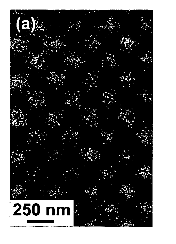
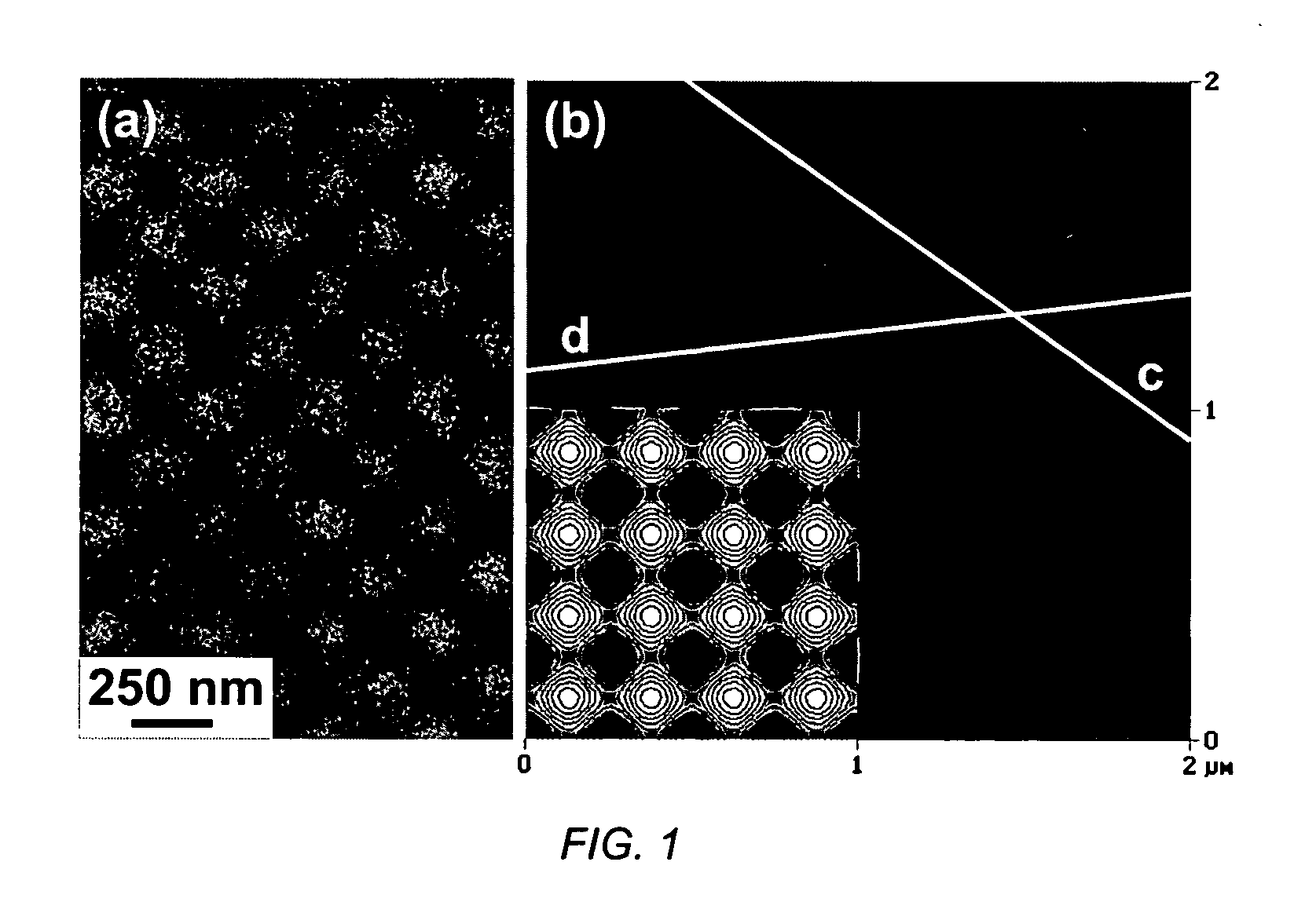
[0022] A PS-PVP copolymer with a weight average molecular weight of 65,200 g / mol, a polydispersity of 1.04, and a PVP volume fraction of 0.12 was synthesized by sequential anionic polymerization technique as previously documented. (H. Yokoyama et al. 2000). Co nanoparticles were synthesized in inverse PS-PVP micelles in toluene by partial pyrolysis of dicobalt octacarbonyl, Co2(CO)8, at 115° C. as reported elsewhere. (F. S. Diana et al.). The synthetic scheme is a variation of the method described by Puntes et al. (2001). Monodisperse amorphous Co nanoparticles with an average diameter of 20±2 nm were obtained after a reaction time of 2 min. The structure of micellar nanoparticles obtained is similar to that of the PS-PVP micelles loaded with tetrachloroauric acid reported by Spatz et al. (2000).

[0023] Two-dimensional periodic nanopatterns were fabricated by means of holographic lithography. The beam from a He—Cd laser operating at wavelength of 325.0 nm was expanded and spatially ...

example 2

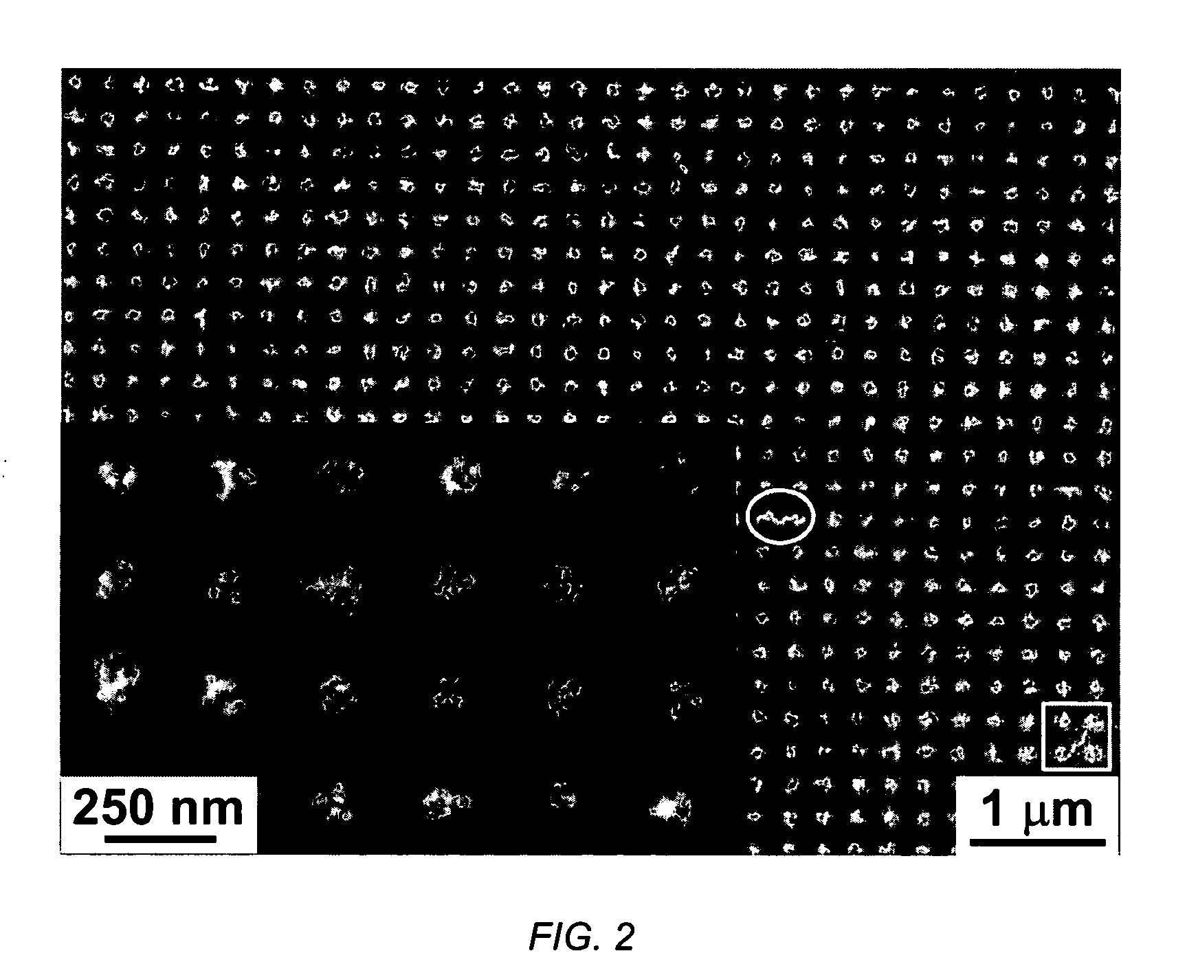
[0029] The spin-coating method was also used to make the self-assembled nanoparticle arrays on the photoresist patterns, and the self-assemblies obtained at 2,000 rpm are shown in the SFM height images of FIG. 3(a)-(c). When a dilute solution (c=0.125 mg / ml) was used, arrays with a sparse population of nanoparticles (2±2 particles per well) were obtained without any particles positioned on top of photoresist mesa regions, as shown in FIG. 3(a). In FIG. 3(a), some wells are shown containing only a single nanoparticle. A more concentrated solution (c=0.50 mg / ml) results in arrays with a dense population of nanoparticles (9±2 particles per well), as shown in FIG. 3(b). The nanoparticle number per well is linearly proportional to the solution concentration at low concentrations as shown in FIG. 4. This implies that the nanoparticle density in the wells can be controlled by simply changing the nanoparticle concentration in the solutions used. If the concentration is further increased to ...


PUM

PropertyMeasurementUnit
aspect ratioaaaaaaaaaa
diameteraaaaaaaaaa

Abstract

A method and resultant device, in which metal nanoparticles are self-assembled into two-dimensional lattices. A periodic hole pattern (wells) is fabricated on a photoresist substrate, the wells having an aspect ratio of less than 0.37. The nanoparticles are synthesized within inverse micelles of a polymer, preferably a block copolymer, and are self-assembled onto the photoresist nanopatterns. The nanoparticles are selectively positioned in the holes due to the capillary forces related to the pattern geometry, with a controllable number of particles per lattice point.

Description

FIELD OF THE INVENTION [0001] The field of art to which the invention pertains relates to the fabrication methods that enable control of the number and positioning of a fixed number of ultra-fine particles or nanoclusters arranged into wells prefabricated on substrates. BACKGROUND OF THE INVENTION [0002] Micro- or nano-patterns of nanoparticles have recently attracted considerable interest due to their possible applications in high-density magnetic storage media (S. Sun et al. 2000), magneto-optical devices (H. Akinaga et al. 2000), and quantum dot displays (K. Suzuki et al. 1999). To obtain these particle patterns, various methods have been successfully applied such as selective wetting on a patterned self-assembled monolayer (SAM) (S. Palacin et al. 1996), layer-by-layer (LbL) self-assembly on a patterned SAM (H. Zheng et al. 2002; and 1. Lee et al. 2002), LbL self-assembly combined with lift-off and / or metal mask techniques (F. Hua et al. 2002a; F. Hua et al. 2002b), electron bea...

Claims


Application Information

Patent Timeline
Patent Type & Authority Applications(United States)
IPC IPC(8): G11B5/706H01F1/00H01F1/153H01L21/4763
CPCB82Y10/00B82Y25/00B82Y30/00H01F1/15316G11B5/706H01F1/009B82Y40/00
Inventor LEE, SEUNG-HEONDIANA, FREDERIC S.BADOLATO, ANTONIOPETROFF, PIERRE M.KRAMER, EDWARD J.
Owner RGT UNIV OF CALIFORNIA
Why Eureka
Try Eureka