[0022] In one broad aspect, the present invention is directed to the configuration of a
spectrometer, which minimizes the negative
impact of the
grating position on performance of the
spectrometer through the selection of an optimal configuration of the
grating position in a spectrum
disperser, and produces constant size images of slit for all wavelengths of
spectral bands up to one
octave wide in any part of an about 400 nm to about 2500 nm spectral range.
[0032] In another broad aspect, the present invention is directed to the production of the multi-channel or line
imaging spectrometer containing a smaller number of easier to produce optical lenses that can be made of a small number of
optical materials.
[0033] The main advantages of a
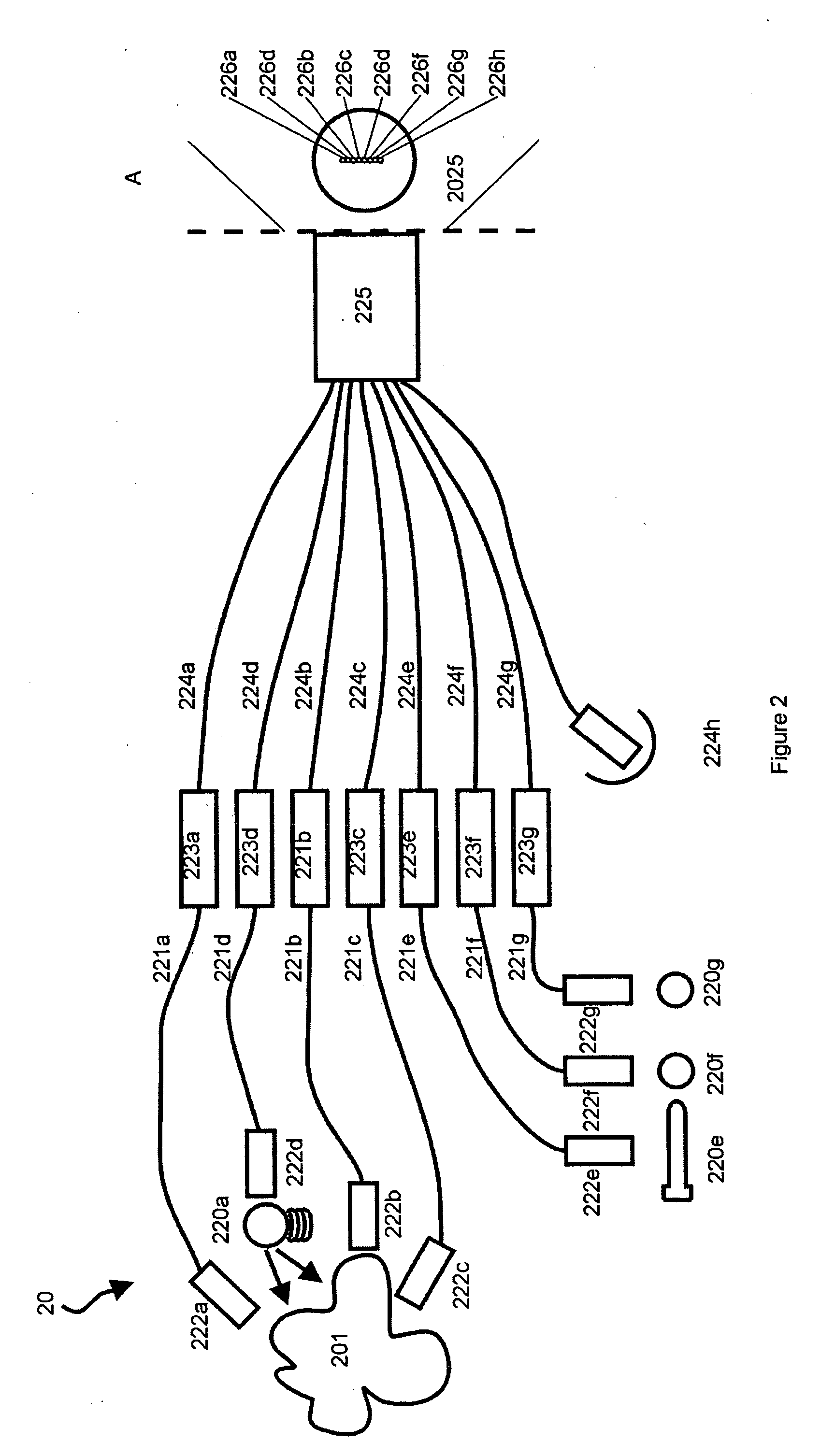
spectrometer designed in accordance with an embodiment of the present invention may become particularly apparent in applications for the simultaneous analysis of spectra from different targets or different points of the same target, especially if the target (e.g. humans) demonstrates spatial instabilities. A proper design of radiation collecting
optics becomes crucial in these kinds of applications if optimal extraction of required information is to be attained. Therefore, in yet another broad aspect, the present invention is directed to a radiation collecting
system for a multi-channel
spectrum analyzer designed in accordance with an embodiment of the present invention, allowing for optimal use of the analyzer.
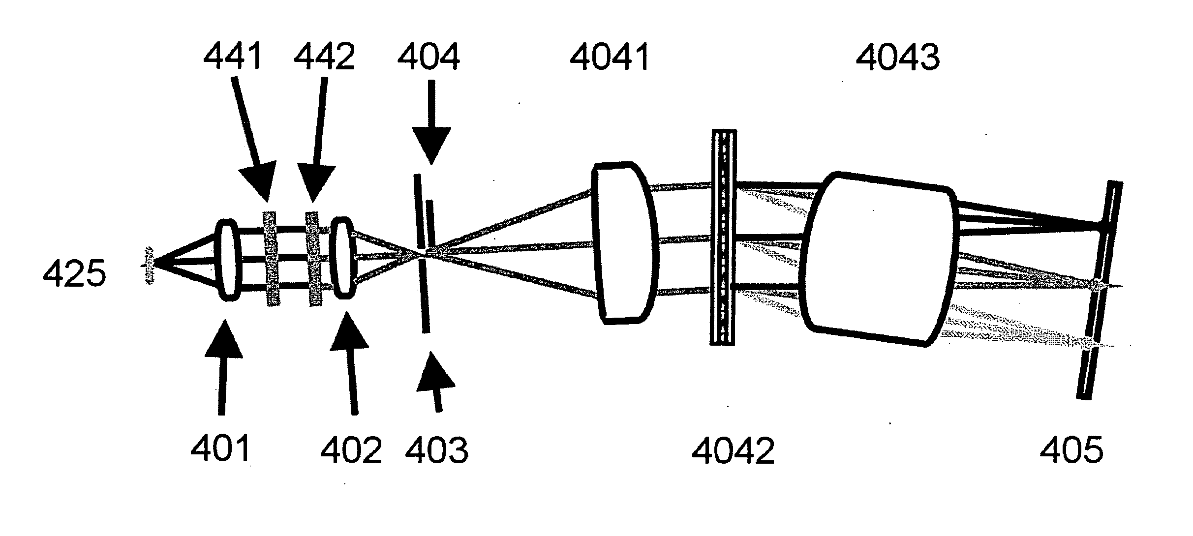
[0036] The focusing objective in this embodiment is designed to produce a
high resolution, flat, undistorted
spectral image of the slit, with constant,
wavelength independent
magnification for a spectral band about one
octave wide placed anywhere between about 400 nm and about 2500 nm of spectral range. In this embodiment, this is achieved with an objective, consisting of three lenses: a relatively thin positive front lens; a very thick, rod-like, negative
meniscus made of material with a higher
refractive index than the front lens; and a relatively thin, positive back lens made of the same material as the front lens. Both the refractive properties of the glasses and the axial thickness of the lenses were selected to produce a focusing objective which simultaneously secures a substantially constant sized focal spot for all wavelengths across the selected working spectral band, and a
wavelength independent, constant size slit image projected on a flat surface of a
photodetector array, essentially perpendicular to the fan axis of the diffracted radiation. Remnant positional
chromaticity of the wide diffracted beams is corrected by the appropriate selection of suitable glasses which forces it to vary linearly with the position on the array; the
impact of this
chromaticity is eliminated by introducing a small tilt to essentially perpendicular to the axis
photodetector array and a corresponding longitudinal and lateral shift of the array, different for different spectral working bands. This degree of freedom allows for the application of the designed objective in any part of the about 400 nm to about 2500 nm spectral range under the condition that the used spectral band is not substantially wider than one octave.
[0037] The present inventors realized that the linear dependence of the positional
chromaticity on the surface of the
detector array does not ensure
linearity of
spectral dispersion; therefore, if there exist three spectral components, with wavelength of the second midway between the wavelengths of the first and third components, the focal spot of the second
spectral component is not necessarily placed at the midway between the remaining two. It was realized that linear
wavelength calibration may not be sufficient for some applications, and a more complex, higher order calibration based on several wavelengths may need to be applied in such cases. This may be unavoidable if the same, relatively simple focusing objective (possibly with antireflection coatings optimized for a working spectral band) in different regions of a wide spectral range is to be used; however, such an objective improves performance and significantly simplifies production process, thereby contributing to the reduction of spectrometer production costs.
[0039] In variant embodiments of the invention objectives can be used in conjunction with reflective gratings, when the dispersion of the
grating, selected working spectral range and configuration of the spectrometer eliminate the problem of the physical interference of the collimating and focusing
optics.

