Production of via hole in flexible circuit printable board

Inactive Publication Date: 2005-07-28
UBE IND LTD
View PDF12 Cites 15 Cited by
  • Summary
  • Abstract
  • Description
  • Claims
  • Application Information

AI Technical Summary

Benefits of technology

[0007] It is an object of the present invention to provide an improved proces

Problems solved by technology

The dry blasting may produce dusts in the blasting procedure.
Therefore, the dry blasting is not advantageously employed in a clean room.
Moreover, abrasive grains attached to the metal/polyimide film composite in t

Method used


Image

  • Production of via hole in flexible circuit printable board
  • Production of via hole in flexible circuit printable board
  • Production of via hole in flexible circuit printable board

Examples


example 1

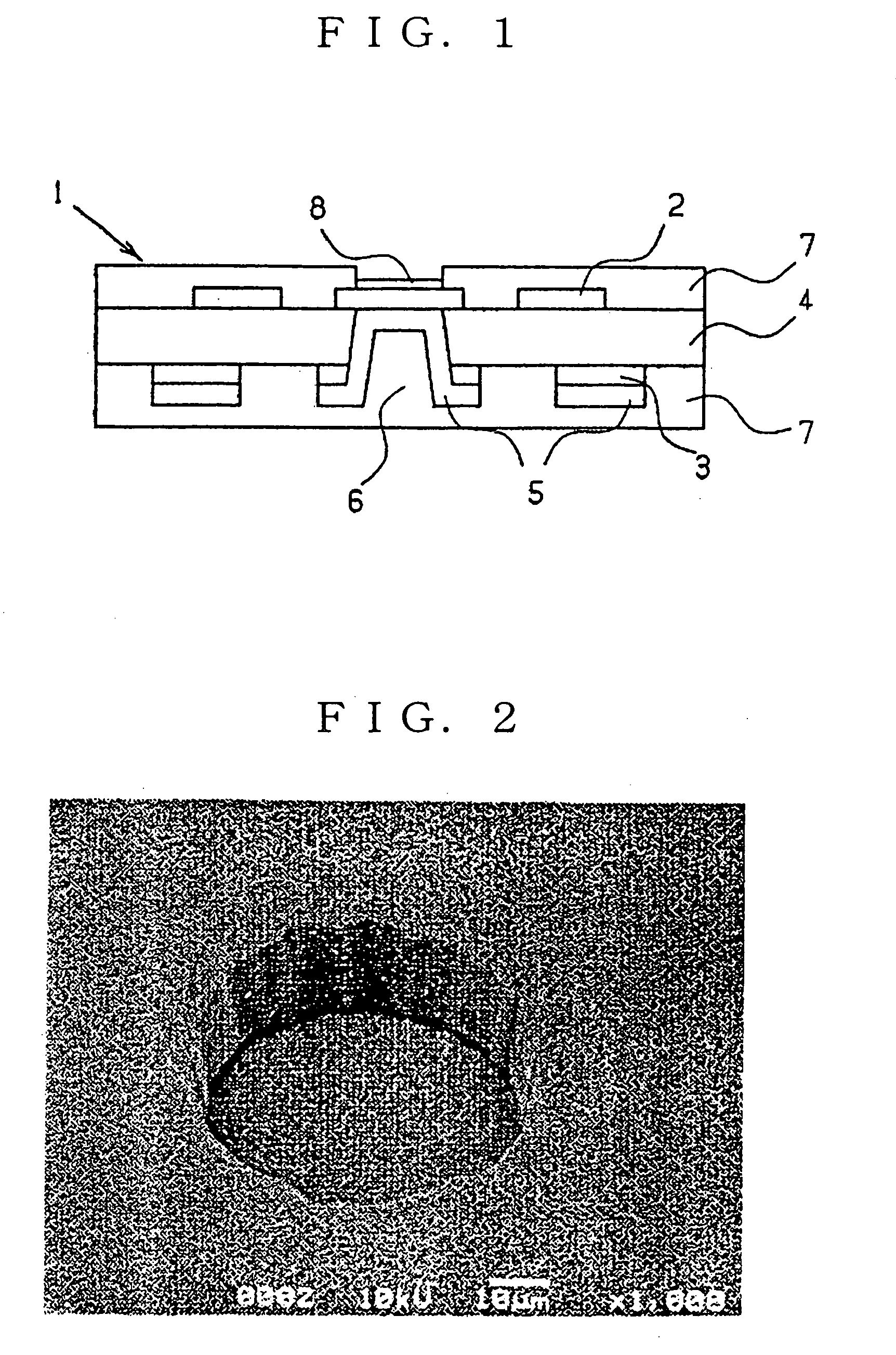
[0067] A metal-coated composite (trade name Upicel N, available from Ube Industries, Ltd.) composed of a three layer polyimide film (thickness: 25 μm) having a thermoplastic surface on each surface side and an electrolytic copper foil (thickness: 9 μm, trade name USLPR2, available from Nippon Electrolytic Co., Ltd.) which was placed on each of the thermoplastic surfaces under pressure and heating is exposed to a UV-YAG laser (Model 5320 available from ESI, wavelength 355 μm), to form simultaneously holes in one copper layer and in the polyimide film. To the holes were subsequently applied a mixture of water and alumina grains (alumina content: 16 vol. %) under an air pressure of 0.2 MPa using a wet-blasting apparatus (available Mako Co., Ltd.), whereby metal flashes and dust in the holes were removed.

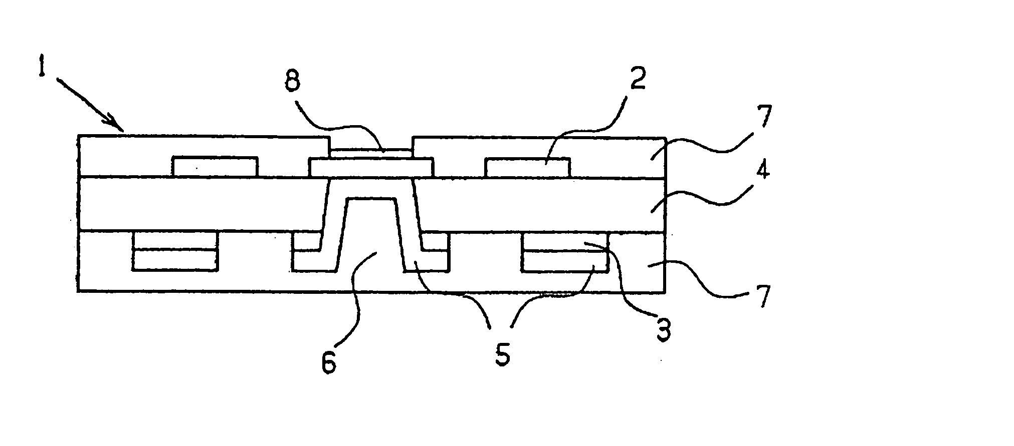
[0068]FIG. 2 shows a section of the hole having been subjected to the above-mentioned wet-blasting.

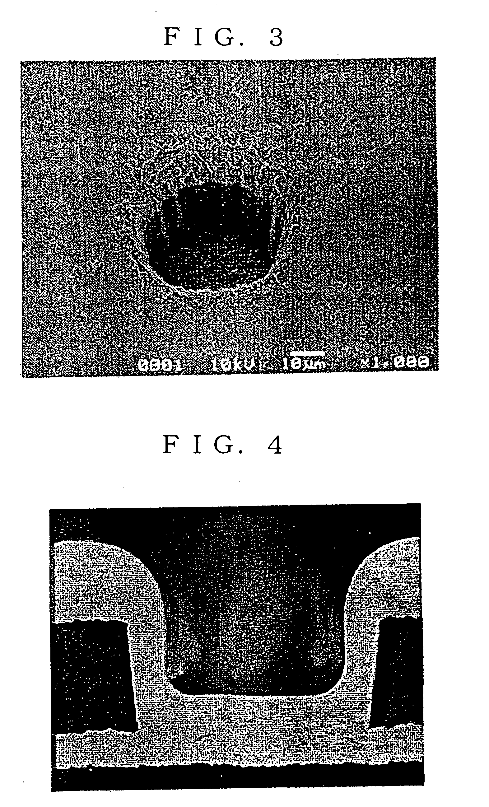
[0069]FIG. 3 shows a section of the hole before having been subjected to the wet-bla...

example 2

[0081] The procedures of Example 1 were repeated except for producing through-holes in the metal-coated polyimide composite film by means of a punch. Thus produced through-holes were then subjected to wet-blasting in the same manner as in Example 1, to give via holes and copper foil having thereon a copper plated layer having a thickness of 12 μm.

[0082] Then, the procedures of Example 1 were repeated to produce a flexible circuit printed board. In the flexible circuit printed board, the copper foils were firmly connected to the copper plated layer, so that no separation was observed at their interfaces when it was heated.


PUM

PropertyMeasurementUnit
Pressureaaaaaaaaaa
Flexibilityaaaaaaaaaa
Photosensitivityaaaaaaaaaa

Abstract

A flexible circuit printable board can be favorably produced by a process composed of steps of forming in a polyimide film having a metal coat on each surface side a via hole penetrating at least one metal coat and the polyimide film; and applying a mixture of liquid and abrasive grains under pressure onto the via hole, whereby smoothing an edge of the via hole and cleaning the via hole.

Description

FIELD OF INVENTION [0001] The present invention relates to a process for producing a via hole in a flexible circuit (or wiring) printable board and further relates to a process for producing a flexible circuit (or wiring) printed board. BACKGROUND OF INVENTION [0002] Recently, sequential build-up boards have been developed in order to package various electronic elements with high density. The sequential build-up boards are made of a plurality of circuit printed boards placed one on another. The circuit printed board is produced by producing electroconductive via holes such as blind holes or through holes in a circuit board having on each surface side a predetermined circuit pattern. [0003] The blind holes are produced by forming holes in a metal coat of a circuit printable board by etching and then forming holes in an insulating substrate of the circuit printable board by means of a punch, a drill, a carbon dioxide laser, a UV-YAG laser, or an excimer laser. [0004] Japanese Patent P...

Claims


Application Information

Patent Timeline
IPC IPC(8): C25D7/00H05K1/00C25D5/34H05K3/00H05K3/06H05K3/26H05K3/28H05K3/42
CPCH05K1/0393H05K3/0035H05K3/0055H05K2201/0154H05K2201/0209Y10T29/49128Y10T29/4913Y10T29/49165Y10T29/49126Y10T29/49117Y10T29/49155H05K2203/025H05K3/00H05K3/42
Inventor KOGURE, RYUICHIROYOKOZAWA, TADAHIROYAMAGUCHI, HIROAKINAKAYAMA, OSAMU
Owner UBE IND LTD
Why Eureka
Try Eureka