Harmonic pulse laser apparatus, and method for generating harmonic pulse laser beams
- Summary
- Abstract
- Description
- Claims
- Application Information
AI Technical Summary
Benefits of technology
Problems solved by technology
Method used
Image
Examples
first embodiment
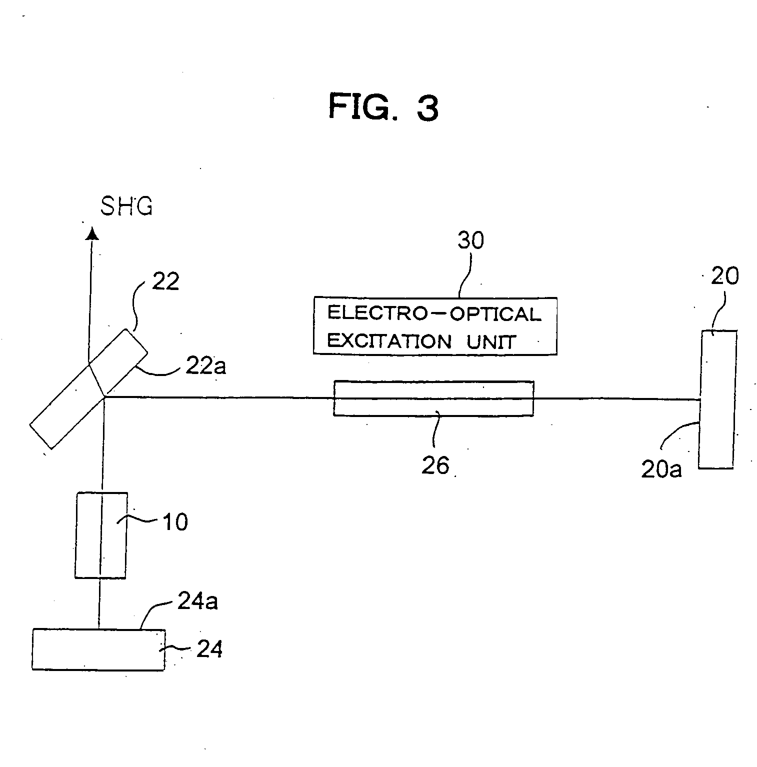
[0054]FIG. 3 shows a configuration of a principal part of a harmonic pulse laser apparatus according to one embodiment. This apparatus has a filded or triangular form optical resonator. More specifically, three (3) mirrors 20, 22, 24 are arranged in the triangular form; a solid-state laser active medium, for example, Nd: YAG rod 26 is disposed on a beam path between an intermediate mirror 22 and one of end mirrors 20; and a KTP crystal 10 is disposed on a beam path between the intermediate mirror 22 and the other end mirror 24. Both end mirrors 20 and 24 are optical resonator mirrors which have high reflectivity to the fundamental wavelength (e.g. 1064 nm) and are arranged optically opposed to each other via the intermediate mirror 22. The intermediate mirror 22 is a harmonic separator output mirror for outputting the second harmonic pulse laser beam to the outside of the resonator.
[0055] The active medium 26 is optically pumped by an electro-optic excitation unit 30. The electro-o...
second embodiment
[0064]FIG. 4 shows a configuration of a principal part of a harmonic pulse laser apparatus according to another embodiment. In this apparatus, the end mirror 20, the harmonic separator output mirror 22, the active medium 26 and the KTP crystal 10 are arranged in the same straight line. More specifically, the active medium 26 is disposed nearer to the end mirror 20 and the KTP crystal 10 is disposed nearer to the harmonic separator output mirror 22. A principal surface 20a of the end mirror 20 is coated with a film which has high reflectivity to the fundamental wavelength (1064 nm). The principal surface 22a of the harmonic separator output mirror 22 is coated with a film which has high reflectivity to the fundamental wavelength (1064 nm) and a film which does not reflect the second harmonic (532 nm). Between the KTP crystal 10 and the active medium 26, a harmonic mirror 32 is disposed facing to the harmonic separator output mirror 22, and a principal surface 32a of the harmonic mirr...
third embodiment
[0072]FIG. 5 shows a configuration of a principal part of a harmonic pulse laser apparatus according to another embodiment. In this apparatus, the end mirrors 20 and 24, the harmonic separate output mirror 22, the active medium 26 and the KTP crystal 10 are arranged in the same straight line. More specifically, the active medium 26 is disposed nearer to the end mirror 20; the KTP crystal 10 is disposed nearer to the end mirror 24; and the harmonic separator output mirror 22 is disposed between the KTP crystal 10 and the active medium 26. However, the harmonic separator output mirror 22 is disposed such that an oblique angle, for example, 45 degrees is formed relative to an optical axis of the resonator. The principal surface of the harmonic separator output mirror 22, i.e., a surface 22a on the side of the KTP crystal is coated with a film which does not reflect the fundamental wavelength (1064 nm) and a film which has reflectivity to the second harmonic (532 nm).
[0073] In this app...
PUM
| Property | Measurement | Unit |
|---|---|---|
| Time | aaaaa | aaaaa |
| Angle | aaaaa | aaaaa |
| Power | aaaaa | aaaaa |
Abstract
Description
Claims
Application Information
 - R&D
- Intellectual Property
- Life Sciences
- Materials
- Tech Scout
- Unparalleled Data Quality
- Higher Quality Content
- 60% Fewer Hallucinations
Browse by: Latest US Patents, China's latest patents, Technical Efficacy Thesaurus, Application Domain, Technology Topic, Popular Technical Reports.
© 2025 PatSnap. All rights reserved.Legal|Privacy policy|Modern Slavery Act Transparency Statement|Sitemap|About US| Contact US: help@patsnap.com


