Electrical field stimulation of eukaryotic cells

Inactive Publication Date: 2005-07-28
MERCK SHARP & DOHME CORP
View PDF11 Cites 19 Cited by
  • Summary
  • Abstract
  • Description
  • Claims
  • Application Information

AI Technical Summary

Benefits of technology

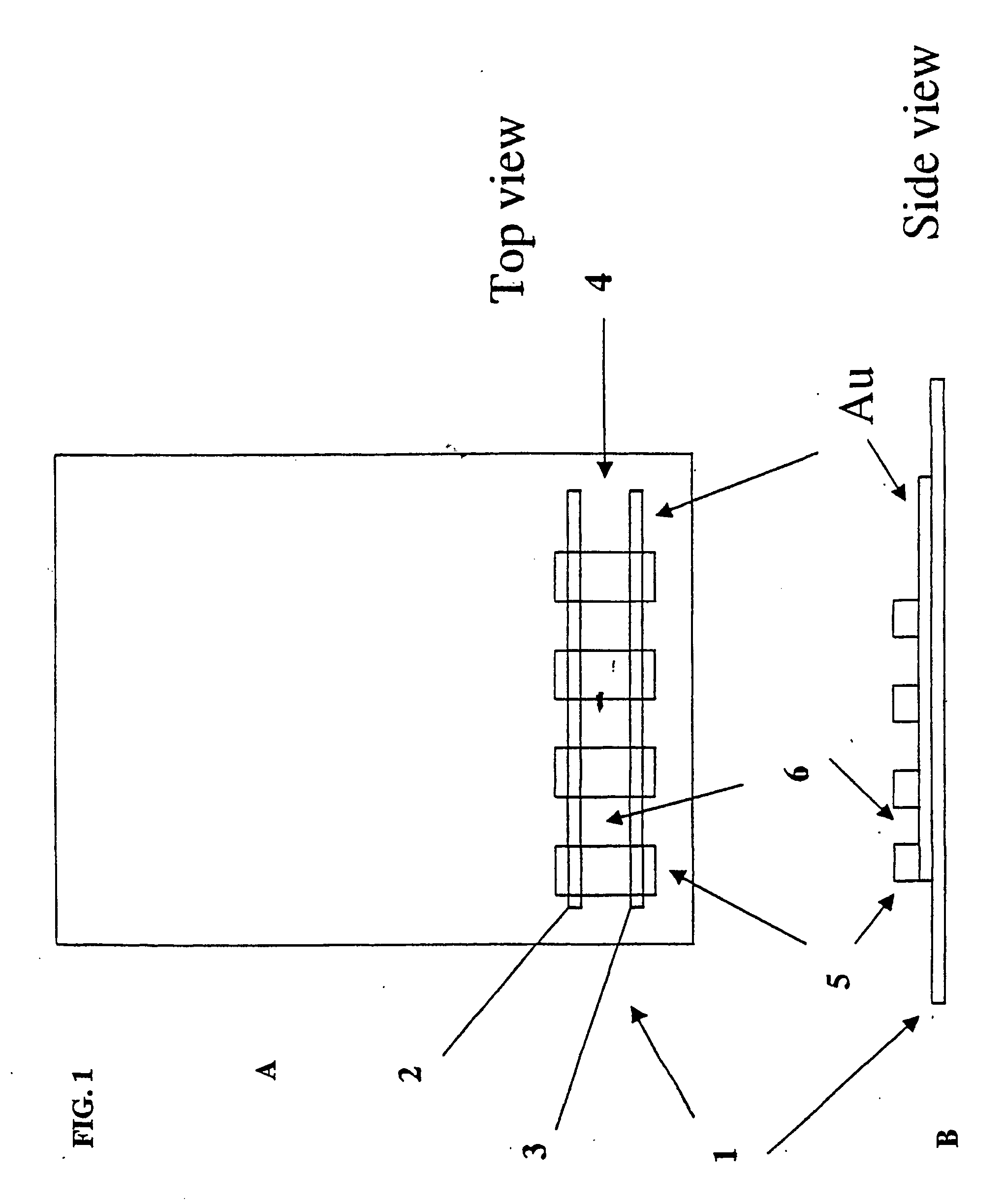
[0017] The present invention is directed to methods of identifying activators and inhibitors of voltage-gated ion channels in which the methods employ electrical field stimulation of the cells via extracellular electrodes in order to manipulate the open/close state transitions of the voltage-gated ion channels. This allows for more convenient, more precise manipulation of these transitions, and, coupled with efficient methods of detecting ion flux or membrane potential, results in methods that are especially suitable for high throu

Problems solved by technology

Unfortunately, current methods of assaying the activity of voltage-gated ion channels are ill suited to the needs of a high throughput screening program.
This has limitations and disadvantages.
Accessing the cell interior may alter the cell's response properties.
The high precision optical apparatuses necessary for micromanipulating the cells and the pipettes make simultaneous recording from more than a few cells at a time impossible.
Given these difficulties, the throughput that c

Method used


Image

  • Electrical field stimulation of eukaryotic cells
  • Electrical field stimulation of eukaryotic cells
  • Electrical field stimulation of eukaryotic cells

Examples


example 1

[0227] In FIG. 24, a preferred system for conducting high throughput screening using EFS stimulation is shown. The system consist of a computer 2402 that comprises an arbitrary waveform generator card 2404 electronically associated with the computer 2402. Custom software was written on the computer 2402 which causes the arbitrary generator card 2404 to generate a pulse voltage waveform (2406) of the appropriate electrical stimulus. The voltage waveform (2406) is applied to the input of eight constant current amplifiers 2408. Each constant current amplifier 2408 services a row on the 96-well sample filter plate 2410. The outputs from the amplifiers 2412 pass through the contacts of electrical relays 2414 allowing the current pulse to be applied to the electrodes 2416.

[0228] The waveform generator card 2404 also generates a 7-bit binary transistor-transistor logic TM value (2418) that represents the address of the well to be excited by the stimulus. In addition, a trigger pulse 2420 ...

example 2

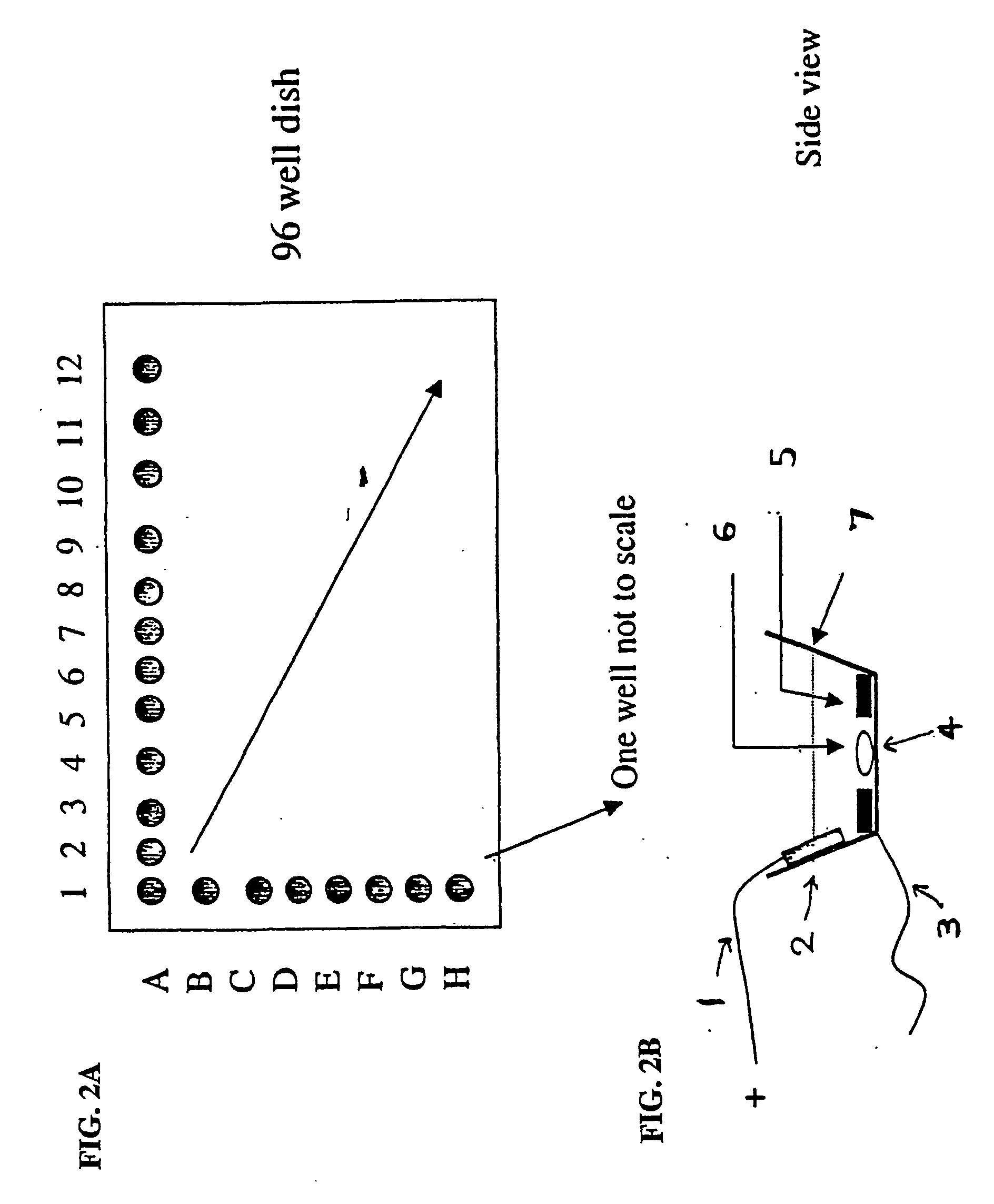
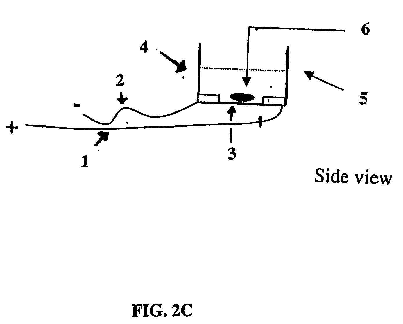
[0237]FIG. 32 represents a photograph of an EFS embodiment 3200 pertaining to an alternative EFS system configuration. The electrode head 2500 is similar to that described above in FIG. 25. However, the configurations of the electrodes, wells and trough are configured differently to further isolate the electrical fields. This reduces cross-talk and interference between wells. For this embodiment, the inventors have adapted Millipore's Multiscreen™ Caco-2 Assay System for use as a EFS system. Information concerning the Multiscreen™ Caco-2 Assay System can be found at http: / / www.millipore.com / publications.nsf / docs / PF1780EN00. The standard commercially available Caco-2 plate system comprises two plates: a membrane- bottom cell growth plate and a 96-well receiver tray. One of the unique characteristics of the Caco-2 system is that it each well has an individual corresponding trough that is accessed basolaterally to each well. Therefore, it supplants the need for a common trough into whi...


PUM

PropertyMeasurementUnit
Electrical conductanceaaaaaaaaaa
Dynamic viscosityaaaaaaaaaa
Electric potential / voltageaaaaaaaaaa

Abstract

Methods of identifying activators and inhibitors of voltage-gated ion channels are provided in which the methods employ electrical field stimulation of the cells in order to manipulate the open/close state transition of the voltage-gated ion channels. This allows for more convenient, more precise experimental manipulation of these transitions, and, coupled with efficient methods of detecting the result of ion flux through the channels, provides methods that are especially suitable for high throughput screening.

Description

CROSS-REFERENCE TO RELATED APPLICATIONS [0001] The subject application is related to co-pending provisional application No. 60 / 304,955, filed Jul. 12, 2001, to which priority is claimed under 35 USC § 119(e).STATEMENT REGARDING FEDERALLY-SPONSORED R&D [0002] Not applicable. REFERENCE TO MICROFICHE APPENDIX [0003] Not applicable. [0004] 1. Field of the Invention [0005] The present invention is directed to methods and associated apparatuses for stimulating eukaryotic cells by the application of electric fields. The electric fields are produced by certain arrangements of electrodes that create an electric potential difference in the environment of the cells, resulting in a change in membrane potential of the cells. The change in membrane potential affects various physiological processes within the cells, including the opening and closing of voltage- gated ion channels. The ability to alter the open / close transitions of voltage-gated ion channels by the application of electric fields as...

Claims


Application Information

Patent Timeline
IPC IPC(8): C12M1/40C12M3/00C12N15/09C12Q1/00C12Q1/02G01N33/15G01N33/50G01N33/68G01N37/00H03C3/09
CPCG01N33/5008G01N33/502Y10T436/11G01N2500/10G01N33/6872
Inventor AUGUSTINE, PAULBUGIANESI, RANDALKATH, GARYMCMANUS, OWENBENNETT, PAULGARYANTES, TINAIMREDY, JOHN
Owner MERCK SHARP & DOHME CORP
Why Eureka
Try Eureka