Substrate determining method

a determining method and substrate technology, applied in the direction of liquid/fluent solid measurement, material electrochemical variables, instruments, etc., can solve the problems of uric acid and acetaminophen, about an error, and an error induced by measurement error

Inactive Publication Date: 2005-07-28
PANASONIC CORP
View PDF2 Cites 25 Cited by
  • Summary
  • Abstract
  • Description
  • Claims
  • Application Information

AI Technical Summary

Benefits of technology

[0018] It is preferable that in the step (b), a central potential of the AC potential is within the range of −0.1 to +0.1 V relative to a redox potential of the electron mediator, and is a potential more positive than a potential that is 0.05 V negative relative to the most negative potential in a potential region where a reaction of the interfering substance at the working electrode is diffusion-controlled.

Problems solved by technology

Although, as thus described, the use of an enzyme can result in realization of measurement with relatively high selectivity of a substrate, a measurement error has been induced by the influence of other substances than a substrate as a subject to be measured which is contained in a sample in the conventionally-used electrochemical measurement where a DC potential is applied.
For example, when an electrochemical measurement is conducted using blood as a sample, easily-oxidizable compounds contained in the blood, such as ascorbic acid (vitamin C), uric acid and acetaminophen, may bring about an error.
In this case, however, a potential difference between GOx and the compound becomes smaller, thereby considerably slowing the transfer rate of electrons therebetween, or preventing the electrons from transferring at all.
As a result, problems may arise that a current for the glucose quantitation does not become large enough to be detectable, or it takes extremely long period of time to detect the current, and further the current is not obtained at all.
It is therefore very difficult in the conventional measurement to predict a measurement error that may occur in measuring the interfering substance concentration in blood and then correct it.

Method used


Image

  • Substrate determining method
  • Substrate determining method
  • Substrate determining method

Examples


example 1

[0059] 10 mL of a phosphate buffer with pH 7, where 0.2 mM of ferrocene carboxylic acid and 4 μM of glucose oxidase were dissolved as a reagent system, was obtained. This 10 mL phosphate buffer was put into a container made of Pyrex Glass to be used as an electrolyte, and a circular platinum disc with a diameter of 3 mm was used as a working electrode while a 2 cm-square platinum plate was used as a counter electrode, to construct an electrochemical cell. A glucose aqueous solution as a sample solution where ascorbic acid was dissolved was added such that the concentrations of ascorbic acid and glucose were 0.5 mM and 20 mM (about 400 mg / dL), respectively.

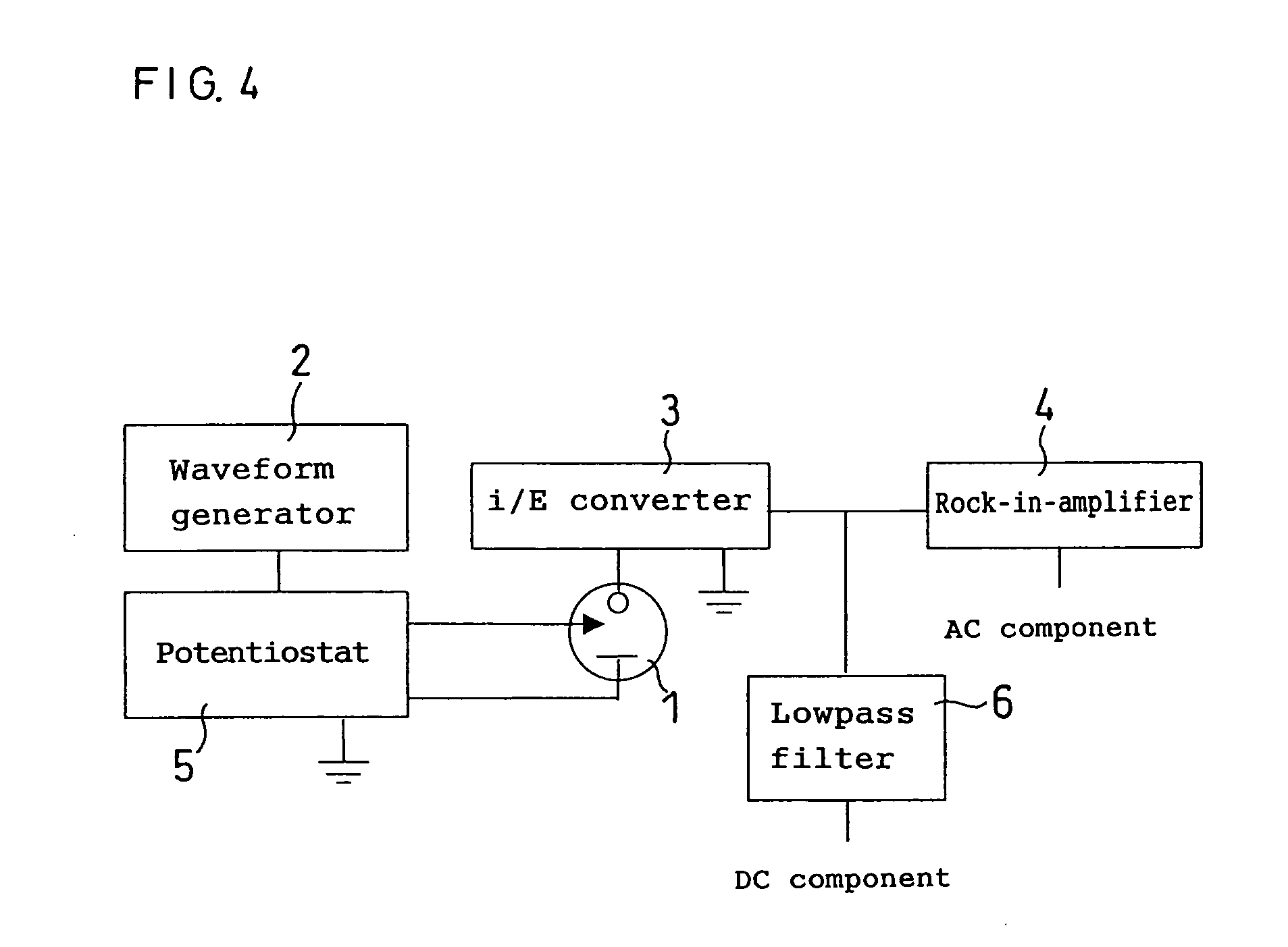
[0060] Then, after the elapse of a certain period of time, an AC potential, having a central potential of +0.1 V relative to the counter electrode and the amplitude of 0.01 V, was applied to the working electrode. A central potential at this working electrode was within the range of −0.1 V to +0.1 V relative to a redox potential o...

example 2

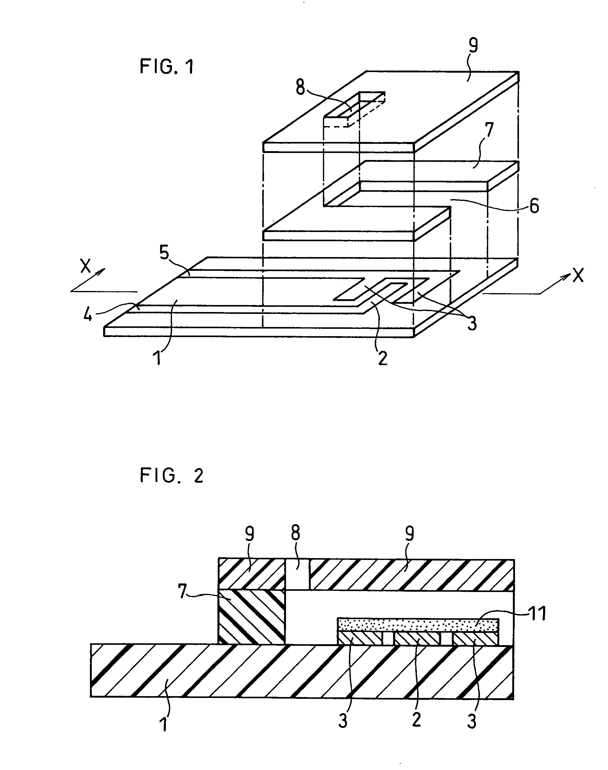
[0064] In the present example, in place of the electrochemical cell used in Example 1, a biosensor produced in the following procedure was used to conduct measurement in the same manner as in Example 1. In the present example, a biosensor with a structure shown in FIGS. 1 and 2 was produced.

[0065]FIG. 1 is an exploded perspective view of the biosensor used in the present example, from which a reagent system has been removed. A resin-made electrode pattern mask was placed on an glass-made electrically insulating base plate 1, and gold was sputtered to form a working electrode 2 and a counter electrode 3. It should be noted that a layer comprising chrome was formed as an adhesive layer between the gold and glass so that the adhesive property therebetween was enhanced. The working electrode 2 and counter electrode 3 were electrically connected to terminals for measurement outside the biosensor through means of leads 4 and 5, respectively.

[0066] After formation of a layer of a reagent...

example 3

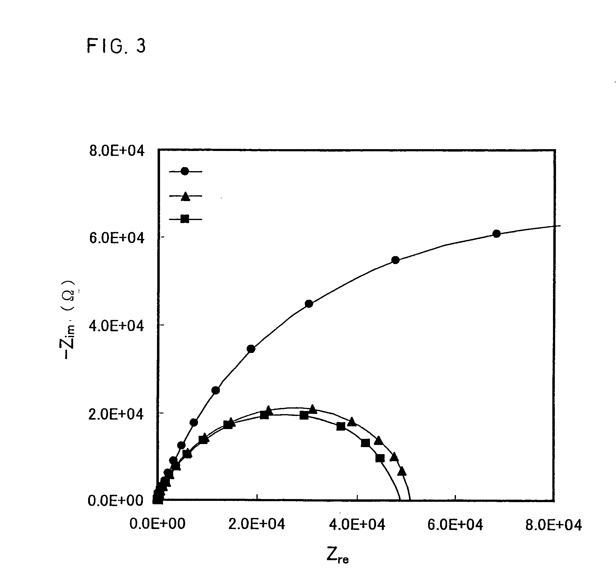
[0075] In the present example, an electrolyte (glucose concentration: 20 mM, ascorbic acid concentration: 0.5 mM) with the same composition as in Example 1 and an electrochemical cell were used. After the lapse of a certain period of time, an AC potential, which had a fixed single frequency, a central potential of +0.1 V when taking the counter electrode as a reference and the amplitude of 0.01 V, was applied to the working electrode. After the lapse of a certain period of time, impedance Z was measured. Next, a DC potential of +0.3 V relative to the counter electrode was applied to the working electrode for a certain period of time to measure a direct current I′ flowing between the working electrode and counter electrode.

[0076] As in Example 1, series of electrolytes with different glucose concentrations were used to conduct measurement and plotting in the same manner as above. As the electrolytes with lower glucose concentrations were used, obtained Z gradually became larger, hav...


PUM

PropertyMeasurementUnit
radiusaaaaaaaaaa
radiusaaaaaaaaaa
radiusaaaaaaaaaa

Abstract

There is provided a method for precisely quantitating a substrate by means of a measurement system with a simple structure without occurrence of a measurement error due to an interfering substance. In a method for quantitating a substrate in a sample solution which contains a dissolved interfering substance and the substrate, by the use of an electrode system and a reagent system, (a) a sample solution which contains a dissolved interfering substance and a substrate is supplied to an electrode system comprising a working electrode and a counter electrode under the existence of a reagent system comprising oxidoreductase and an electron mediator; (b) an AC potential is applied to the working electrode, to cause a redox reaction of the electron mediator: (c) an electric signal produced on the basis of the redox reaction is measured by means of the electrode system; and (d) the substrate is quantitated on the basis of the electric signal.

Description

TECHNICAL FIELD [0001] The present invention relates to a method for electrochemically quantitating a substrate contained in a sample with the use of oxidoreductase. BACKGROUND ART [0002] There have been developed plenty of methods for simple measurement and quantitation of a specific substrate present in a sample. In particular, methods for measurement and quantitation with high selectivity by utilizing a substrate-selective catalytic action of an enzyme has recently been drawing much attention, and some of these methods have been used as methods for quantitating a specific element in body fluid in the field of clinical examinations, and further in the field of self-examinations by ordinary people. [0003] As an example of methods for quantitating and measuring a substrate in a sample, an electrochemical quantitation method of glucose is described. Glucose oxidase (hereinafter abbreviated to GOx) is an enzyme that selectively catalyzes oxidation of glucose. When a certain amount of ...

Claims


Application Information

Patent Timeline
Patent Type & Authority Applications(United States)
IPC IPC(8): C12Q1/00C12Q1/26C12Q1/32
CPCC12Q1/001G01N27/3273C12Q1/32C12Q1/26
Inventor KUWABATA, SUSUMUNAKAMINAMI, TAKAHIRO
Owner PANASONIC CORP
Why Eureka
Try Eureka