[0042] One
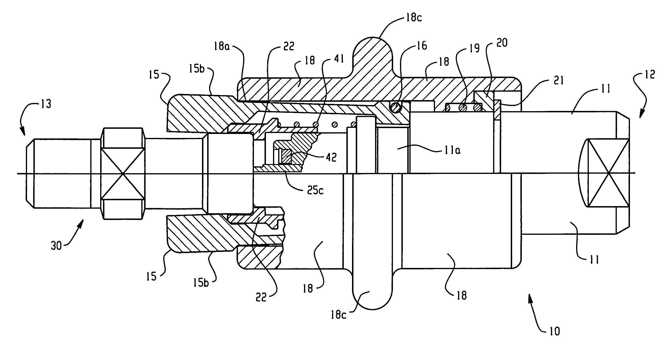
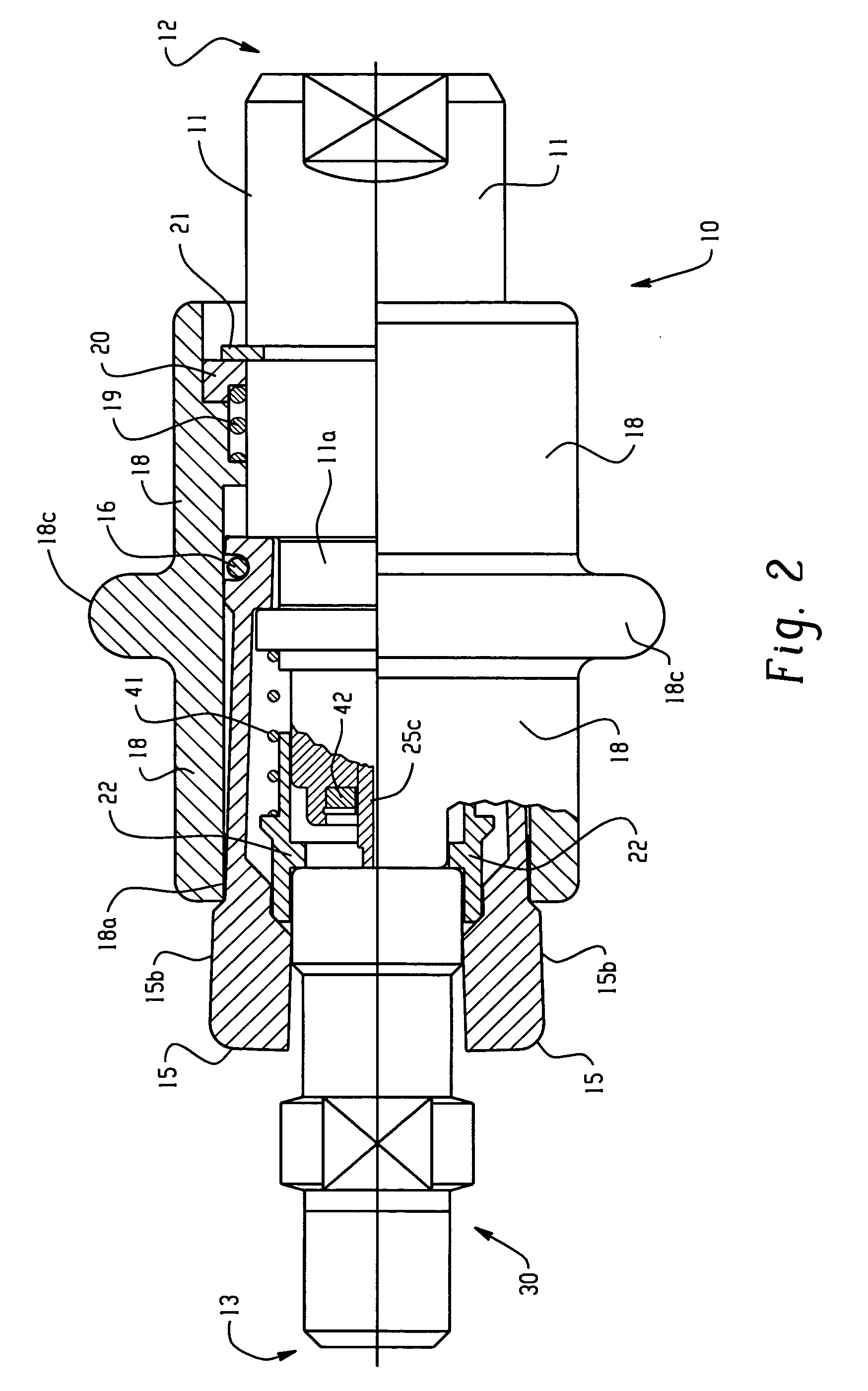
advantage of the present invention is that the components of coupling 10 were configured to significantly reduce the volume of fluid released when the coupling 10 releases the fitting 30. This was accomplished by (i) significantly reducing the volume of fluid that will necessarily be released when the coupling 10 releases the fitting 30 and (ii) decreasing the required travel of parts before the flow of fluid is stopped. More specific to the implementation shown in the figures, the volume of fluid released when the coupling 10 releases the fitting 30 is reduced by (i) significantly reducing the volume of the bores within the
check valve 25 downstream of seat 26 and (ii) significantly reducing the travel distance of parts required for
check valve 25 to stop the flow of fluid.
[0043] As to reduced volume of fluid released, the bore 25d of first pin 25b is about 1 mm (about 0.375 inches) in
diameter and is about 5.5 mm (about 0.210 inches) deep. The radial bore 25e of first pin 25b is about 1 mm (about 0.0375 inches) in
diameter and about 1.5 mm (about 0.0575 inches) deep. Therefore, the fixed volume of fluid that will escape from first pin 25b when coupling 10 releases fitting 30 is about 5.5 mm3 (about 0.0003 cubic inches). Similarly, the bore 25f of second pin 25c is about 1 mm (about 0.0375 inches) in
diameter and is about 28.5 mm (about 1.125 inches) deep. Therefore, the fixed volume of fluid that will escape from second pin 25c when coupling 10 releases fitting 30 is about 22 mm3 (about 0.0012 cubic inches). Also, the fact that tip 25j of second pin 25c is inserted into bore 35 of fitting 30 allows additional expelled
fluid volume to be reduced, because that tip 25j fills a significant volume inside bore 35 that might otherwise be filled with high-pressure fluid.
[0044] As to reduced amount of travel required for
check valve 25 to stop the flow of fluid through first pin 25b, when in use, the radial bore(s) 25e are displaced from seal 26 in the range of from about 0 mm to about 13 mm, preferably by only about 6.5 mm. Thus, when fitting 30 is released, the first pin 25b need only move within that range or that distance to seat, thereby stopping the flow of fluid through first pin 25b.
[0045] Although the improved rapid connection coupling and fitting according to the present invention can be used in virtually any fluid transfer application, because of their relative ease of use and relatively quiet connection and disconnection the improved rapid connection coupling and fitting according to the present invention have particular utility in the application of filling mobile oxygen containers, e.g., with home-based
oxygen cylinder fillers in the home environment and with transfill devices at dealers, etc. The connection and fitting are particularly suited to oxygen refilling in the home environment and can be incorporated in the home oxygen refilling systems taught by Invacare U.S. Pat. No. 5,988,165 and in copending Invacare U.S.
patent application Ser. Nos. 09 / 154,442 (filed on Sep. 16, 1998), and 09 / 695,612 (filed on Oct. 24, 2000), all of which are hereby incorporated by reference. In the aforementioned patent and both applications, the coupling 10 of the present invention would be used between the compressor 100 and the cylinder 500, with the coupling 10 being in fluid connection downstream of the compressor and the fitting 30 being preferably incorporated into the cylinder 500 to facilitate the rapid and easy connection and disconnection of the cylinder 500 with respect to the coupling 10. Additionally, in the later application, the coupling 10 of the present invention can also replace the fill connector 845 in the unit shown in FIG. 13 and described in that application.
[0046] Those skilled in the art will appreciate which materials will be suitable and / or required for the particular coupling application in mind for the coupling 10 and fitting 30 according to the present invention. For example, for the high-pressure oxygen application,
brass, stainless steel, PTFE, EDPM, POM, and Gleitmo 595
lubrication are all acceptable for parts coming into contact with the oxygen. Thus, in the coupling 10 and fitting 30 for use with high-pressure oxygen, the O-rings (16, 26a, 26c, 34f, 34g, and 36a) are preferably made of EPDM, the
backup rings (26d and 36b) are preferably made of PTFE, part 26b (L-shape in cross section) is preferably made of POM, the springs and retaining rings (snap rings) contacting the oxygen (43, 45, and 38) are preferably made of 301 or 302 stainless steel,
retaining ring (snap ring) 21 is preferably made of coated stainless steel, sleeve 18 is preferably made of an aluminum
alloy (0.8% silicium, 0.8% iron, 0.5-1%
manganese, 0.4-1.8%
magnesium, 0.1%
chromium, 0.8%
zinc, 0.3% others together, and the rest being aluminum), and the remaining
metal pieces (11, 15, 22, 20, 29, 25b, 25c, 26e, 33, 34e, and 34d) are preferably made of
brass (57-59%
copper, 2.5%-3.5% lead, 0.1% aluminum, 0.5% iron, 0.5%
nickel, 0.4%
tin, 0.2% others together, with the rest being
zinc).
[0047] As discussed above, the connection fittings 30 according to the present invention preferably include a cylindrical portion 31a. FIGS. 12 and 13 show two fittings having cylindrical portions 31a of different lengths, corresponding to two different pressures. Fitting 30 can, for example, be designated to be a lower pressure fitting, e.g., 2000 psi, and fitting 30′ can, for example, be designated to be a higher pressure fitting, e.g., 3000 psi. Similarly by varying the length of the corresponding portion of jaws 15, as shown in FIGS. 3 and 14-16, it is possible to designate a low pressure coupling 10 and a
high pressure coupling 10′. Thus, one can designate a low-pressure fitting 30 (i.e., a low pressure cylinder) that will function with a low pressure coupling 10 (FIG. 3) but will not function with a
high pressure coupling 10′ because of physical interference between a structure 50 and the jaws 15 (see FIG. 16), thereby preventing a cylinder rated for only 2000 psi from being used with a coupling capable of pressurizing that cylinder to 3000 psi. Similarly, it is possible to designate a high-pressure fitting 30′ (i.e., a high-pressure cylinder) that will function with a low pressure coupling 10 (FIG. 15) and will also function with a
high pressure coupling 10′ (see FIG. 14). This type of differentiation
system (varied lengths of cylindrical portions 31a and corresponding jaw portions 15), can also be used to differentiate couplings 10 and fittings 30 based on other criteria, e.g., different gases, etc.


