
Method for control of mercury

a technology for mercury and flue gas, applied in the field of mercury control, can solve the problems of difficult capture of elemental mercury, inability to collect and dispose of fly ash, etc., and achieve the effect of inherent safety advantag

Inactive Publication Date: 2005-08-04
DOWNS WILLIAM +1
View PDF74 Cites 47 Cited by
  • Summary
  • Abstract
  • Description
  • Claims
  • Application Information

AI Technical Summary

Benefits of technology

[0012] There is good reason to expect that the precipitation reaction proceeds faster than the reduction reactions. Specifically, in the case of the precipitation reaction, both reactants are well mixed in the gas phase. Thus, as they diffuse from the gas to the gas / liquid interface both reactants can react instantly at that interface. By contrast, the reduction reactions require that the reactants, i.e., the Hg+2 and the transition metal ion, diffuse in the liquid phase to a reaction plane in the liquid. Liquid phase diffusion is orders of magnitude slower than gas phase diffusion. Therefore, the oxidized mercury will rapidly precipitate as cinnabar in the scrubber and thereby prevent the reduction of that mercury back to vaporous elemental mercury. The precipitation of mercury as cinnabar has a distinct advantage over other mercury sequestering methods in that it converts mercury to a very insoluble form. In this way, the mercury should be inert and effectively removed from the food chain.
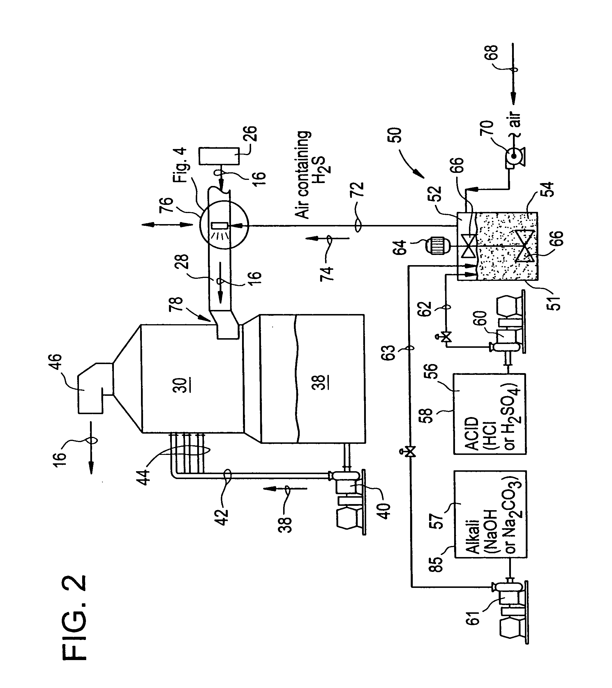
[0013] Accordingly, one aspect of the present invention is drawn to an improvement in a method using a wet scrubber for receiving and scrubbing an industrial gas containing mercury with a wet scrubber slurry, the improvement comprising: adding hydrogen sulfide to the industrial gas; and scrubbing the industrial gas in the wet scrubber. The method according to the present invention is particularly suited to the task of reducing mercury emissions in an industrial process which burns coal in a furnace to produce an exhaust flue gas, including conveying the exhaust flue gas through a dust collector and adding hydrogen sulfide to the flue gas before it enters the wet scrubber, or within the wet scrubber.

Problems solved by technology

Therefore, it cannot be collected and disposed of along with fly ash like the other metals.
It was generally expected that the oxidized mercury would be easily captured and the elemental mercury would be difficult to capture.

Method used


Image

  • Method for control of mercury
  • Method for control of mercury
  • Method for control of mercury

Examples


Embodiment Construction

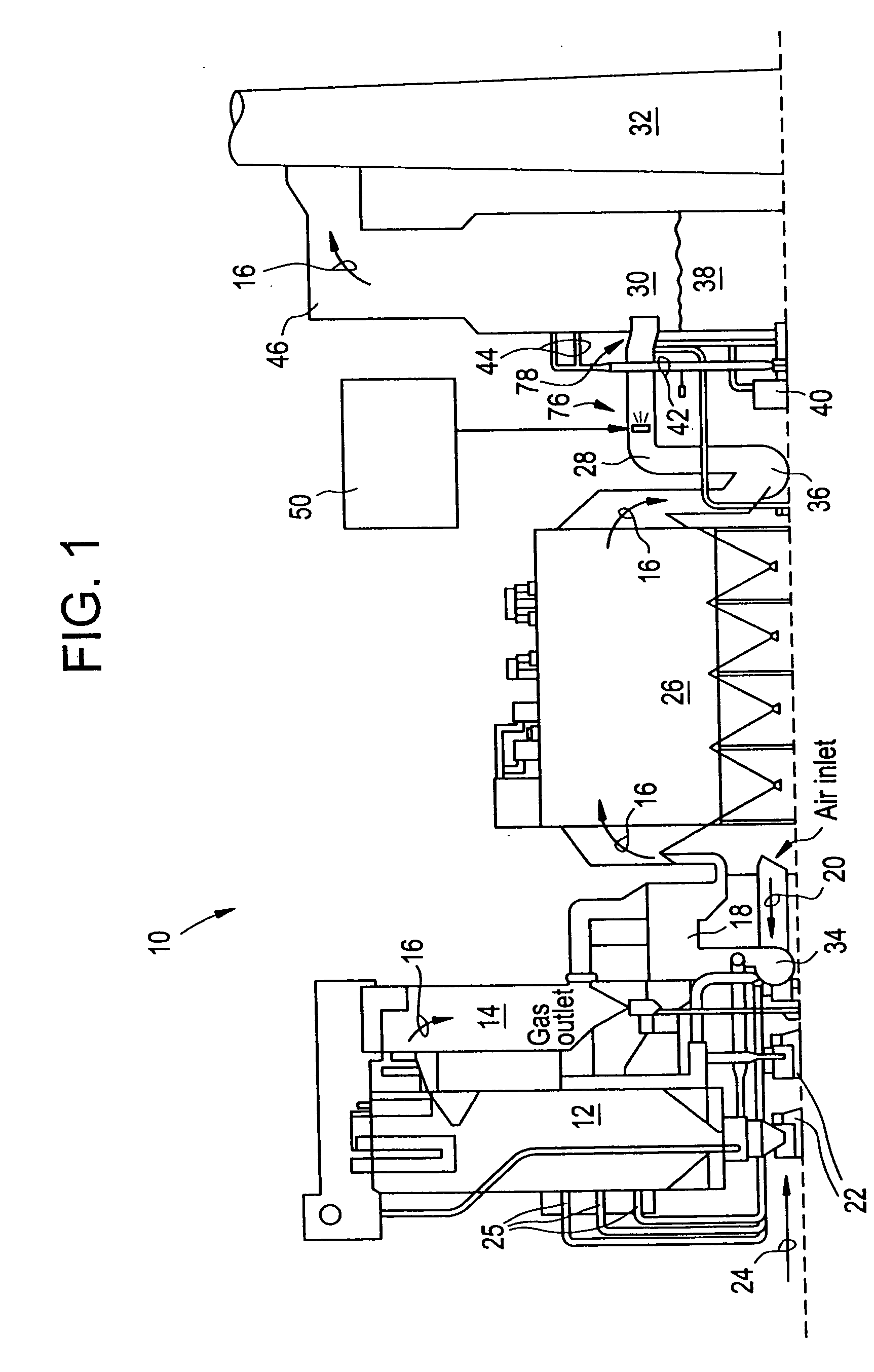
[0025] Referring to the drawings generally, wherein like reference numerals designate the same or functionally similar elements throughout the several drawings, and to FIG. 1 in particular, FIG. 1 illustrates a coal-fired utility boiler installation of the type used by utilities in the generation of electric power, generally designated 10, and which represents one type of industrial process to which the present invention is applicable. In its broadest form, the present invention comprises a method for removing mercury from the flue gas generated during the combustion of fossil fuels or solid wastes through the use of trace amounts of hydrogen sulfide. Of course, while the aforementioned coal-fired utility boiler installations are but one example, and the method of the present invention will likely first find commercial application to the removal of mercury from the flue gases produced by such utility boiler installations which combust such fossil fuels, any industrial process using ...


PUM

PropertyMeasurementUnit
Fractionaaaaaaaaaa
Concentrationaaaaaaaaaa
Vapor pressureaaaaaaaaaa

Abstract

A method and apparatus for reducing mercury in industrial gases such as the flue gas produced by the combustion of fossil fuels such as coal adds hydrogen sulfide to the flue gas in or just before a scrubber of the industrial process which contains the wet scrubber. The method and apparatus of the present invention is applicable to installations employing either wet or dry scrubber flue gas desulfurization systems. The present invention uses kraft green liquor as a source for hydrogen sulfide and / or the injection of mineral acids into the green liquor to release vaporous hydrogen sulfide in order to form mercury sulfide solids.

Description

[0001] This is a divisional application of U.S. Ser. No. 09 / 894,558 filed Jun. 28, 2001, which is a divisional application of U.S. Ser. No. 09 / 282,817 filed Mar. 31, 1999, now U.S. Pat. No. 6,284,199 B1, and the text of the aforementioned patent applications are hereby incorporated by reference as though fully set forth herein.[0002] The subject matter of the present invention was developed under a research contract with the U.S. Department of Energy (DOE), Contract No. DE-FC22-94PC94251, and under a grant agreement with the Ohio Coal Development Office (OCDO), Grant Agreement No. CDO / D-922-13. The governments of the United States and Ohio have certain rights in the invention.FIELD AND BACKGROUND OF THE INVENTION [0003] The present invention relates generally to the field of combustion and flue gas cleanup methods and apparatus and, in particular, to a new and useful method and apparatus for removing mercury from the flue gases generated during the combustion of fossil fuels such as...

Claims


Application Information

Patent Timeline
IPC IPC(8): B01D47/06B01D53/64B01D53/78F23J15/00F23J15/02
CPCB01D47/06B01D53/64B01D53/78F23J15/003F23J2219/60F23J2215/60F23J2217/102F23J2219/40F23J15/02
Inventor DOWNS, WILLIAMBAILEY, RALPH T.
Owner DOWNS WILLIAM
Learn More