Wire-free, dual-mode calibration instrument for high energy therapeutic radiation

a dual-mode calibration and radiation technology, applied in the direction of instruments, radiation intensity measurement, x/gamma/cosmic radiation measurement, etc., can solve the problems of cumbersome and time-consuming quality assurance checks, and it is difficult to construct a quality assurance instrumen

Active Publication Date: 2005-08-11
STANDARD IMAGING
View PDF18 Cites 23 Cited by
  • Summary
  • Abstract
  • Description
  • Claims
  • Application Information

AI Technical Summary

Benefits of technology

[0011] The present invention provides a radiation beam checker that may verify flux profiles and constancy for a wide variety of radiation energies and modes. Several features contribute to this versatility. First, the beam checker may receive radiation from either of two directions, flipping to receive electrons through one side and photons through the other. In this way, a single set of detectors may be optimized for either of two different radiation modes. Second, rather than relying on a single filtered and unfiltered detector to determine energy level, the present invention may use multiple detectors, each having a different filtration to provide data for a more sophisticated energy discrimination function accurate over a wide energy range. Visual fiducia on both surfaces of the beam checker allow alignment to be determined by flux measurements from the multiple flux-detectors without the need for photosensitive edge detectors that would be required on both surfaces.
[0012] One embodiment of the present invention permits wire-free operation simplifying manipulation of the beam checker without requiring radio communication that may be difficult to establish in the environment of the radiotherapy machine. An additional feature of one embodiment of the present invention is automatic linkage of data to energy levels to minimize necessary operator input. In one embodiment, the present invention may employ a new construction technique for ionization detectors simplifying the manufacture and improving the consistency of multi-detector systems.

Problems solved by technology

Such quality assurance checks can be cumbersome and time consuming particularly when multiple pieces of test equipment must be used, for example, as would be required to calibrate a radiotherapy machine that provides both electron beams and photon beams at a variety of energy levels.
It is difficult to construct a quality assurance instrument that works for a wide variety of different radiation energies and different radiation modes, e.g. electrons or photons, equally well.

Method used


Image

  • Wire-free, dual-mode calibration instrument for high energy therapeutic radiation
  • Wire-free, dual-mode calibration instrument for high energy therapeutic radiation
  • Wire-free, dual-mode calibration instrument for high energy therapeutic radiation

Examples


Embodiment Construction

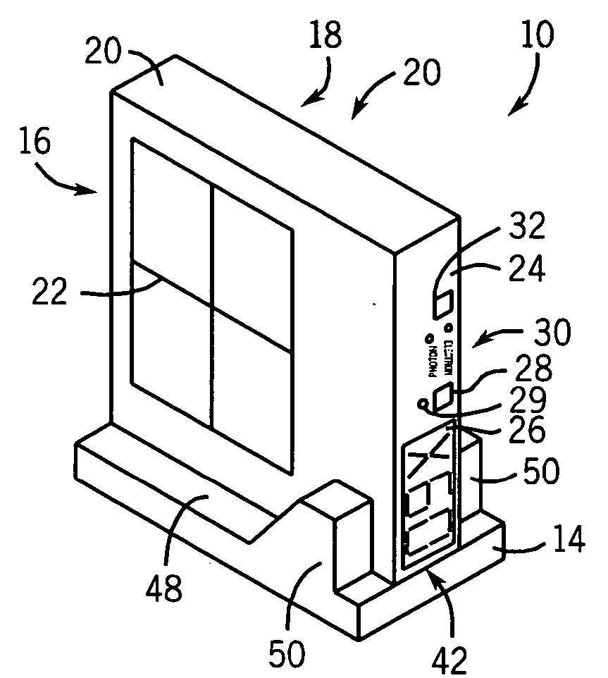
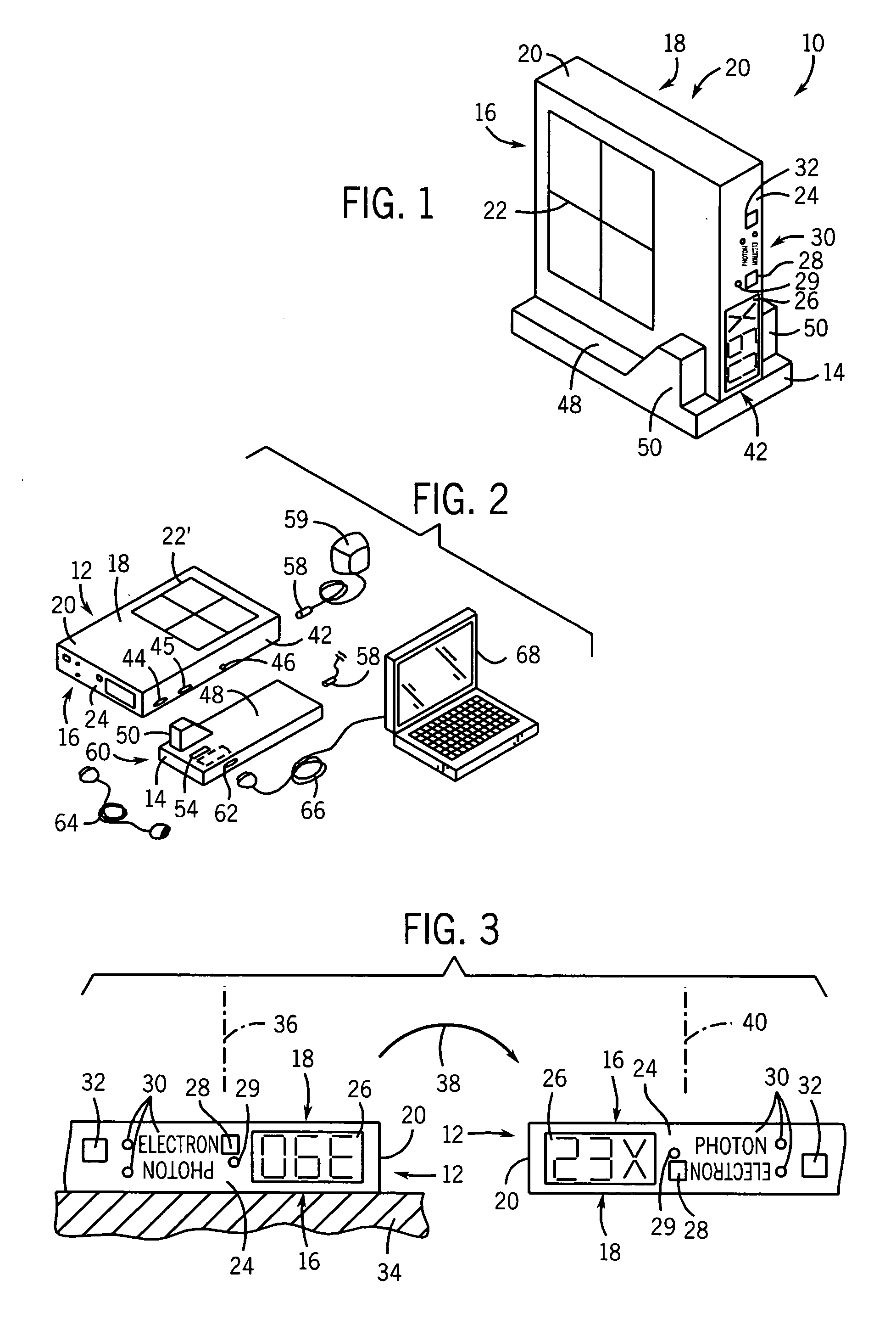
[0041] Referring now to FIG. 1, the beam checker 10 of the present invention provides a mobile detecting unit 12 having a generally rectangular, box-shaped housing 20 providing a first photon-receiving face 16 opposed to a second electron-receiving face 18.

[0042] Referring also FIG. 2, a portion of the photon-receiving face 16 and electron-receiving face 18 is marked with a target 22 defining an area of radiation exposure and thus providing a means for aligning the housing 20 of the mobile detecting unit 12 with a light field or laser crosshair provided by standard radiotherapy machines, as will be described. Typically, the target 22 or 22′ is 20 cm by 20 cm and includes a crosshair dividing the target area into equal quadrants.

[0043] Referring to FIGS. 2 and 3, a first side wall 24 of the housing 20 holds a three-character, 1.2 inch tall, seventeen-segment light emitting diode (LED) alphanumeric display 26, a reset button 28 and a separate bicolor LED 29, radiation mode captions ...


PUM


Abstract

An instrument for checking quality of therapeutic x-ray and electron radiation provides modes optimized for both electrons and for photons obtained by physically flipping the unit to interpose the necessary build-up material between the radiation beam and contained detectors. The invention provides an improved method of constructing ionization detectors for improved energy discrimination using such detectors and wire-free operation.

Description

CROSS-REFERENCE TO RELATED APPLICATIONS [0001] - - STATEMENT REGARDING FEDERALLY SPONSORED RESEARCH OR DEVELOPMENT [0002] - - BACKGROUND OF THE INVENTION [0003] The present invention relates to quality assurance instruments for medical radiotherapy equipment used for radiation treatment of tumors or the like. [0004] Cancerous tumors may be treated by irradiating the tumor with high-energy photons or electrons (henceforth both termed “radiation”). [0005] Such radiotherapy relies in part on the fact that tumor tissue is more sensitive than normal tissue to such high-energy radiation. Nevertheless, the radiation dose must be carefully controlled to limit the exposure of healthy tissue while ensuring sufficient radiation is received by the tumor. [0006] Radiation dose may be controlled by a variety of means including shutters for collimating the radiation beam to the area of the tumor, filters for varying the intensity of radiation within the area of the tumor, and control of the exposu...

Claims


Application Information

Patent Timeline
Patent Type & Authority Applications(United States)
IPC IPC(8): H01J47/02
CPCH01J47/02A61N2005/1076
Inventor SCHMIDT, DANIEL G.SOMMERFELDT, MYLES L.DEFEVER, KEVIN L.BONDE, THOMAS C.
Owner STANDARD IMAGING
Why Eureka
Try Eureka