

Plasma reactor and purification equipment
a technology of purification equipment and reactor, which is applied in the direction of machines/engines, lighting and heating equipment, separation processes, etc., can solve the problems of large equipment scale, complicated architecture, and high cost, and achieves easy progress, low cost, and gentle rise and fall.
- Summary
- Abstract
- Description
- Claims
- Application Information
AI Technical Summary
Benefits of technology
Problems solved by technology
Method used
Image

Examples
embodiment 1
(Effect of Embodiment 1)
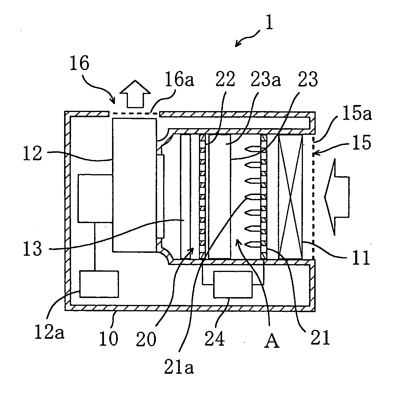
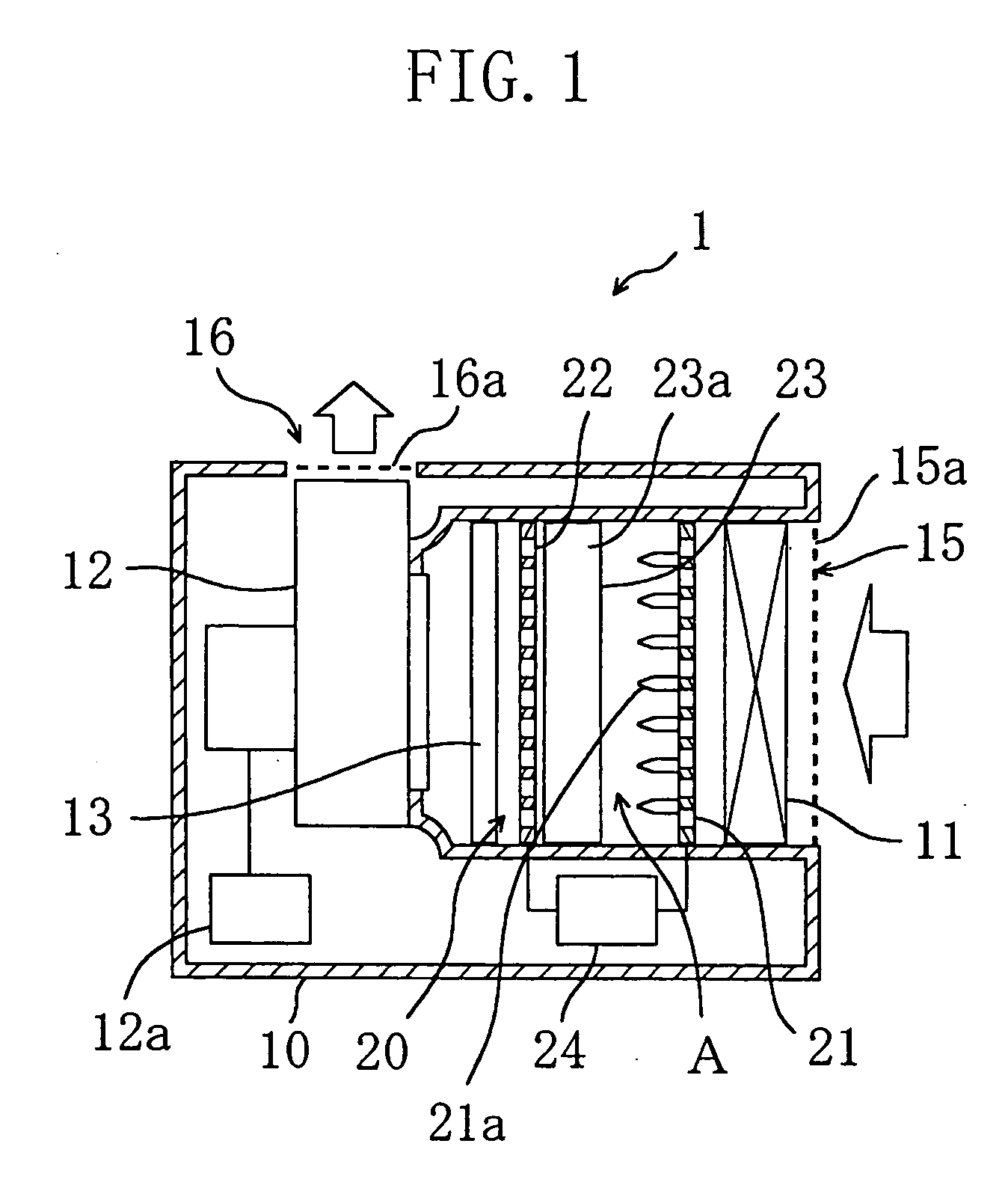
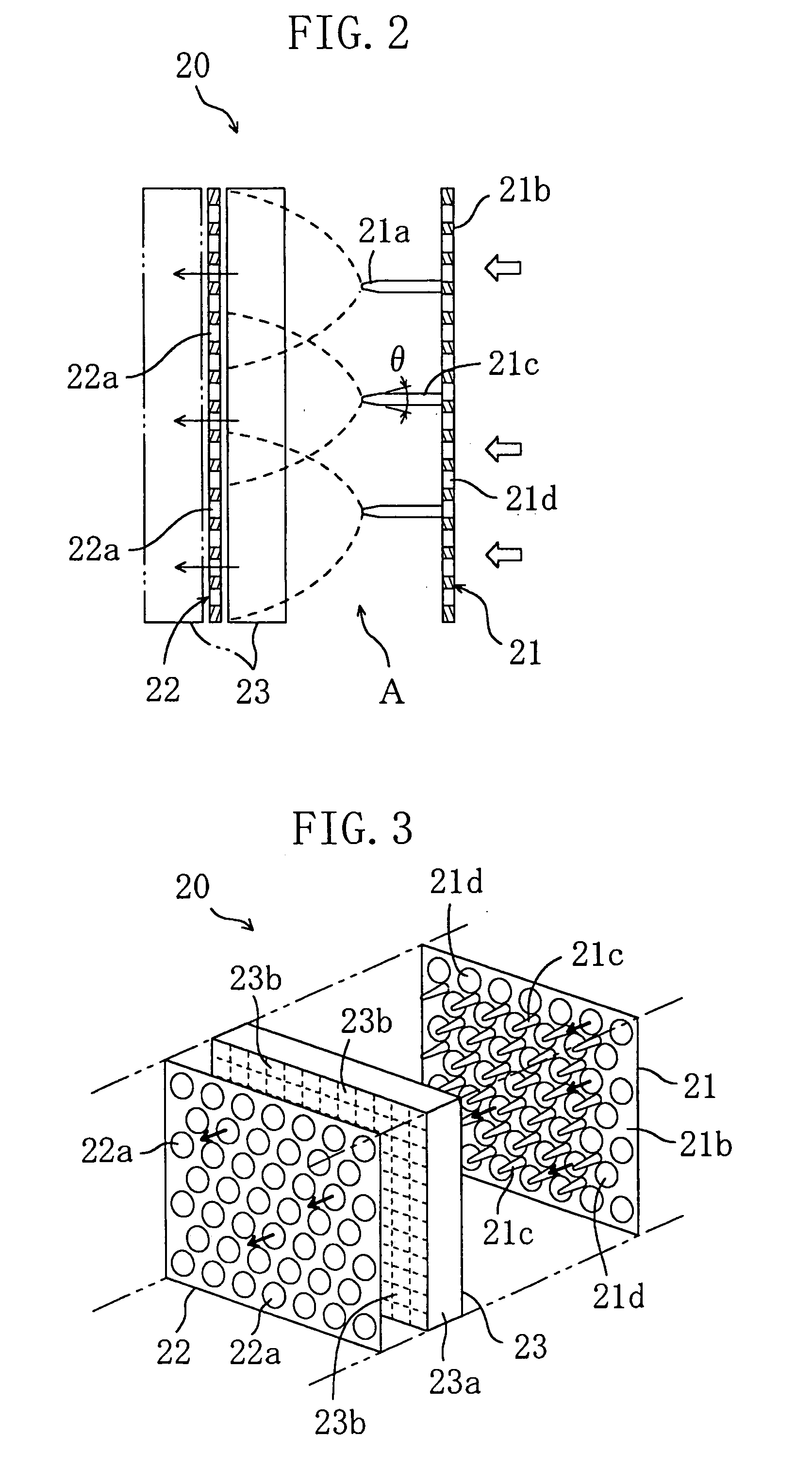
[0136] In Embodiment 1, the point angle θ of the first electrode 21 is 60 degrees, preferably not less than 30 degrees and not more than 90 degrees and more preferably not less than 60 degrees and not more than 90 degrees, and the pointed portion is rounded, so that the small electric arc can easily progress while spreading in a wide range. Thus, the streamer discharge is caused in a wide region. Since the generation region of the streamer discharge is thus widened by specifying the shape of the pointed portion of the first electrode 21, there is no need to use a pulse source for supplying a steep pulse high voltage with a small pulse width. Therefore, a pulse source for supplying a pulse with gentle rise and fall, an AC power supply or even a DC power supply can be used. Accordingly, the cost can be suppressed, and the whole equipment can be prevented from having large scale and being complicated. Also, since there is no need to use a steep pulse, the discha...
example 1
[0139] When a manganese-based catalyst is used as the catalyst, the catalyst may preferably include not less than 30 mass % and not more than 40 mass % of Mn, MnO2 or Mn2O3. Alternatively, the content of Mn, MnO2 or Mn2O3 in the catalyst may be not less than 10 mass % and not more than 60 mass %.
[0140] As shown in a graph of FIG. 6 in which the ordinate indicates toluene decomposition efficiency attained by using the plasma reactor 20 and the abscissa indicates the content of MnO2, a catalyst including not less than 10 mass % and not more than 60 mass % of MnO2 can attain comparatively high decomposition efficiency, and in particular, a catalyst including not less than 30 mass % and not more than 40 mass % of MnO2 can attain very high decomposition efficiency.
example 2
[0141] The treatment member 23 may include, as the catalyst, a mixture or a composite oxide of a manganese oxide and an oxide of at least one of iron, cerium, europium, lanthanum and copper (hereinafter referred to as the specified oxide). Also, in the treatment member 23, the composition ratio of the manganese oxide in the catalyst is not less than 20% and not more than 50%, and the composition ratio of the specified oxide is not less than 80% and not more than 50%. Furthermore, the catalyst may include several kinds of manganese oxides with different oxidation numbers, such as MnO2 and Mn2O3.
[0142] When a catalyst including manganese, iron and cerium is used, the catalyst may be prepared as follows: An aqueous solution of manganese nitrate hexahydrate is prepared as a manganese compound, to which cerium nitrate hexahydrate is added as a cerium compound, and iron nitrate nonahydrate is added to the resultant as an iron compound, so as to give a solution A. On the other hand, a sol...
PUM
| Property | Measurement | Unit |
|---|---|---|
| Fraction | aaaaa | aaaaa |
| Fraction | aaaaa | aaaaa |
| Percent by mass | aaaaa | aaaaa |
Abstract
Description
Claims
Application Information