Devices Employing Colloidal-Sized Particles

a technology of colloidal particles and devices, applied in the direction of instruments, piston pumps, laboratory glassware, etc., can solve the problems of consuming significantly less space, requiring difficult etching procedures, and limiting the use of colloidal particles in such devices

Inactive Publication Date: 2005-08-11
COLORADO SCHOOL OF MINES
View PDF27 Cites 16 Cited by
  • Summary
  • Abstract
  • Description
  • Claims
  • Application Information

AI Technical Summary

Benefits of technology

[0018] In another embodiment, a photonic filter or switch is provided that utilizes the diffraction property of ordered colloidal particles. In one embodiment, the photonic filter or switch comprises the previously noted elements of a photonic device and a pair of polarizers that are crossed relative to one another, with one polarizer associated with each plate. When no electrical field is being applied to the colloidal particles, the unordered state of the colloidal particles prevents white light from passing through the crossed polarizers. However, when an electrical field is applied to the colloidal particles to place the particles in an ordered state, certain frequencies of white light are depolarized and capable of passing through both polarizers. By stacking such structures, different colors or changes in intensities are achieved. In another embodiment, the cross polarizers are eliminated. In this embodiment, when no electrical field is being applied to the colloidal particles, white light passes through both plates. However, when an electrical field is applied to the colloidal particles, white light directed to one of the plates is diffracted by the ordered colloidal particles such that an observers appropriately positioned relatively to the other plate will observe certain frequencies of white light, i.e., certain colors. This embodiment is also capable of being used to selectively reflect light.

Problems solved by technology

The need to mix, administer and separate fluids at these length scales has long been a limiting factor in such devices.
Actuators that may be micromachined, such as electrostatic, thermopneumatic, electromagnetic and bimetallic actuators consume significantly less space than conventional actuators but often require difficult etching procedures.
Microfluidic flow controllers, such as chip-top valves and pumps, have also historically been plagued by size limitations imposed by actuators.
While some current microfluid handling devices and techniques enable functional devices at microscales, they may also impose significant constraints upon potential device capability, flexibility and performance.
While molecular separation by electrophoresis has been exploited for particular applications such as nucleic acid sequencing and the development of protein targeted chemotherapy, the complications discussed here are generally considered obstacles to μTAS intended for applications with heterogeneous fluids such as blood or urine.
Additionally, the scale of flow controllers, such as pumps and valves, has not kept pace with the miniaturization of flow channels themselves, thus limiting the ultimate size at which practical devices may be created.
While functionally simple and conceptually elegant, the pneumatic actuation scheme still hinders the ultimate utility of these devices through the need for interfacing to external equipment.
These structures, while only tens of microns in size and very efficient at measuring and responding to specific environmental conditions, such as pH and temperature, are quite limited in their sensing capabilities and ability to produce a broad range of feedback options.
The need to mix, pump, and direct fluids at very small length scales, however, has long been the limiting factor in the development of microscale systems, thus generating a tremendous amount of interest in the burgeoning field of microfluidics.
While these microfluid handling techniques enable functional devices on microscopic length scales, they also impose unique constraints upon potential device capability, flexibility and performance.
The fabrication and actuation of these devices, however, has been limited to bulk environments external to microfluidic geometries.
Because no practical implementation scheme has been developed for their incorporation into functioning microfluidic systems, they have not realized their suggested potential as microfluidic pumps and valves.
To date, the primary difficulty in the use of colloidal systems for such applications has been the fabrication of large arrays of colloidal particles into specific lattices with specific defect structures and tailored optical properties.
However, development of technologically relevant colloidal crystals is hindered by the difficulty in uncoupling the variation of colloid-colloid interactions from the lattice structures that do form.

Method used


Image

  • Devices Employing Colloidal-Sized Particles
  • Devices Employing Colloidal-Sized Particles
  • Devices Employing Colloidal-Sized Particles

Examples


Embodiment Construction

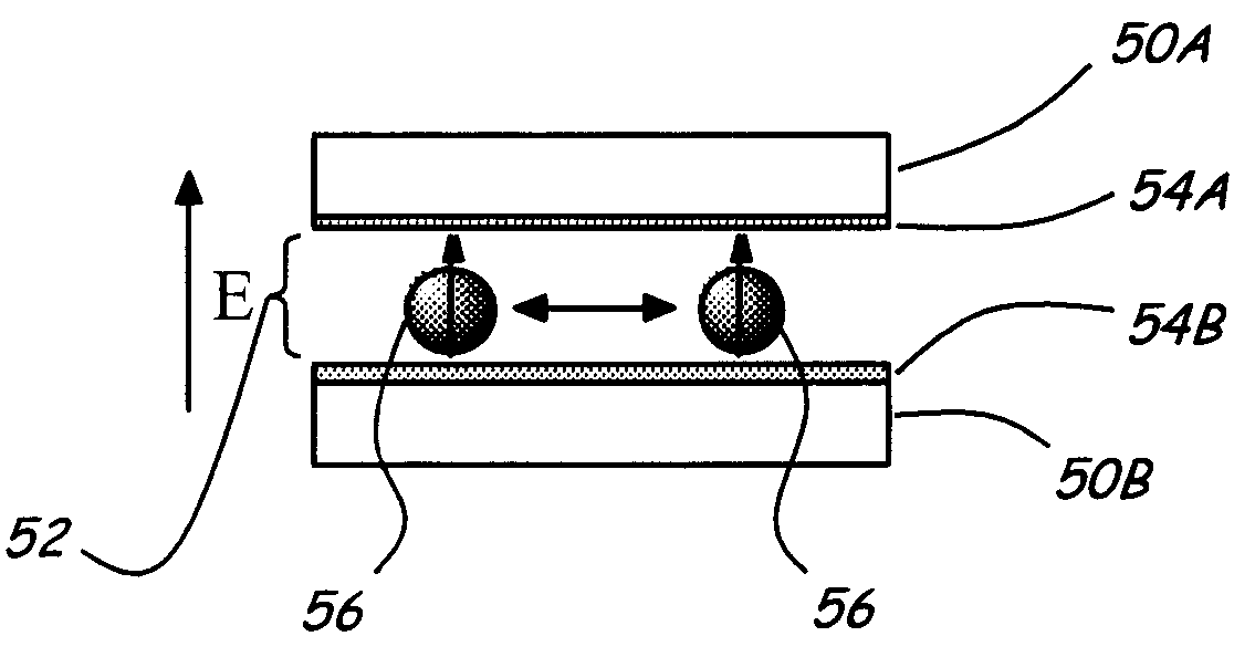
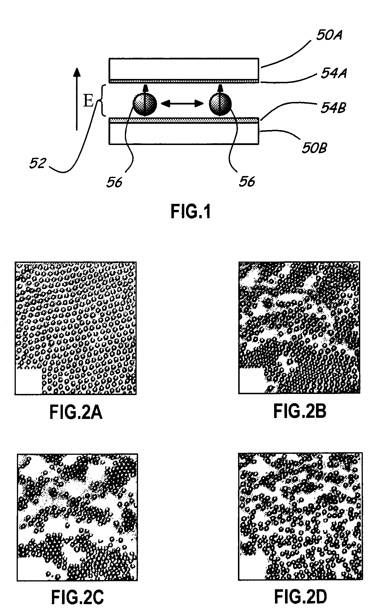
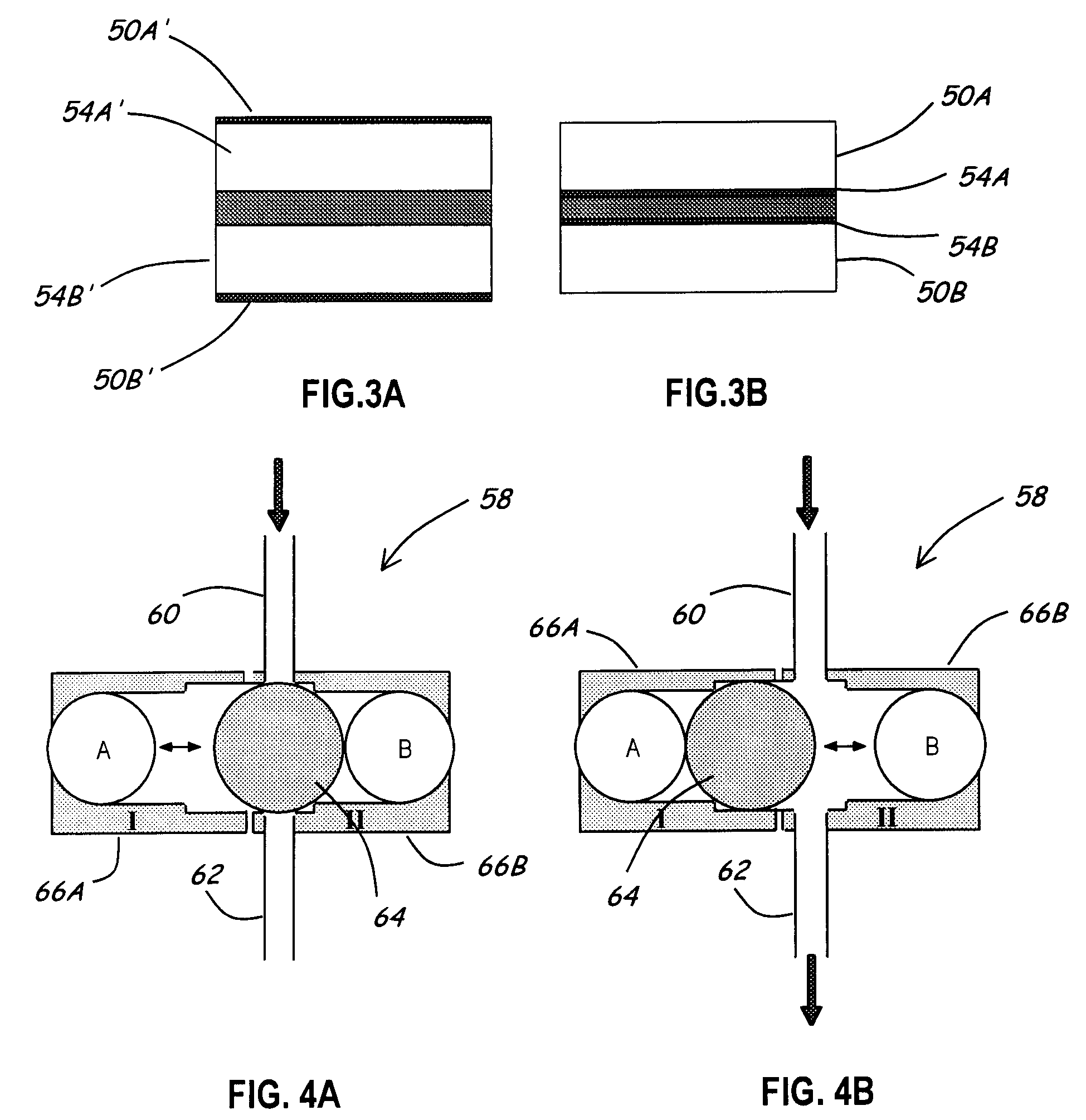
[0064] Described is the application of colloidal manipulation techniques using fields for the purpose of fluid control on the microscale. Colloidal particles, a generic term describing micron and submicron sized bits of solid matter suspended in a fluid medium, can respond to the application of external fields. Charged colloidal particles will migrate in an electric field due to the electrophoretic body force exerted by the field. Similarly, magnetizable particles can be translated or aligned with magnetic fields. Additionally, a monodisperse suspension of colloidal particles confined between two plates separated by roughly a single particle diameter will repulsively order in the presence of an electric field applied perpendicularly to the confining plane. Furthermore, colloidal particles can be trapped and manipulated individually with focused laser beams; a technique commonly referred to as “optical trapping” or “optical tweezing”. These four methods of colloidal particle manipula...


PUM


Abstract

The present invention relates to the use colloidal particles to realize photonic and microfluidic devices. In particular embodiments, colloidal particles are used to realize microfluidic a two-way valve, three-way valve, check valve, three-dimensional valve, peristalsis pump, rotary pump, vane pump, and two-lobe gear pump. In certain embodiments, actuation of an active element in the microfluidic structure is accomplished by electrophoresis, the use of an optical trap or “tweezer”, or the application of an electric field or magnetic field. In other embodiments, the application of an electrical field to colloidal particles that are substantially constrained to two dimensional movement is used to realize wave guides, filters and switches for optical signals.

Description

CROSS-REFERENCE TO RELATED APPLICATIONS [0001] The present application is a divisional of U.S. patent application Ser. No. 10 / 138,799, filed on May 3, 2002, that is a continuation of provisional patent application No. 60 / 288,346, filed on May 3, 2001, and provisional patent application No. 60 / 289,504 filed on May 8, 2001, all of which are incorporated herein, in their entireties, by reference.FIELD OF THE INVENTION [0002] The present invention is directed to the use of colloidal-size particles to realize microfluidic and photonic devices. BACKGROUND OF THE INVENTION [0003] The “lab-on-a-chip” concept, in which three-dimensional microfabrication techniques borrowed from the integrated circuit industry are employed to create electrical circuits that interface with chemical or biological systems upon micropatterned substrates, has gained significant research interest in recent years, and has been heralded as the next silicon revolution. The drastic reduction in length scales from conve...

Claims


Application Information

Patent Timeline
Patent Type & Authority Applications(United States)
IPC IPC(8): B01L3/00F04B17/00F04B19/00F04B43/12F04C2/063F04C13/00F15C5/00F16K99/00
CPCB01F13/0059G02F2202/32B01L3/502738B01L2200/0647B01L2300/0861B01L2400/0415B01L2400/043B01L2400/0454B01L2400/0616B01L2400/0622B01L2400/0633F04B17/00F04B19/006F04B43/12F04C2/063F04C13/00F16K99/0001F16K99/0023F16K99/0028F16K99/0034F16K99/004F16K99/0046F16K99/0051F16K2099/0074F16K2099/0094G02F1/0147B01F13/0818B01F33/30B01F33/452
Inventor MARR, DAVID W.M.GONG, TIEYINGOAKEY, JOHNTERRAY, ALEXANDER V.
Owner COLORADO SCHOOL OF MINES
Why Eureka
Try Eureka