Nanoscale transduction systems for detecting molecular interactions

a transduction system and molecular interaction technology, applied in nanoinformatics, nanomedicine, instruments, etc., can solve the problems of limited application of this stochastic detection theory in other fields, such as life sciences, subject to the fundamental limits of background noise, etc., and achieve the effect of single molecule detectability

Inactive Publication Date: 2005-08-11
RGT UNIV OF CALIFORNIA
View PDF31 Cites 55 Cited by
  • Summary
  • Abstract
  • Description
  • Claims
  • Application Information

AI Technical Summary

Benefits of technology

[0007] The present invention relates to higher order nanoscale transduction systems (i.e. “nanomachines”) that are capable of demonstrating single molecule detectability. One aspect of the present invention is a method that involves binding a nanostructure and an associated structure to a target and reversibly altering interaction between the nanostructure, the associated structure and

Problems solved by technology

Traditional assays do not make use of this dynamic, and therefore are subject to the fundamental limits of background noise described above.
The extension of this sto

Method used


Image

  • Nanoscale transduction systems for detecting molecular interactions
  • Nanoscale transduction systems for detecting molecular interactions
  • Nanoscale transduction systems for detecting molecular interactions

Examples


example 1

Production of an Oscillatory Nanoscale Signal

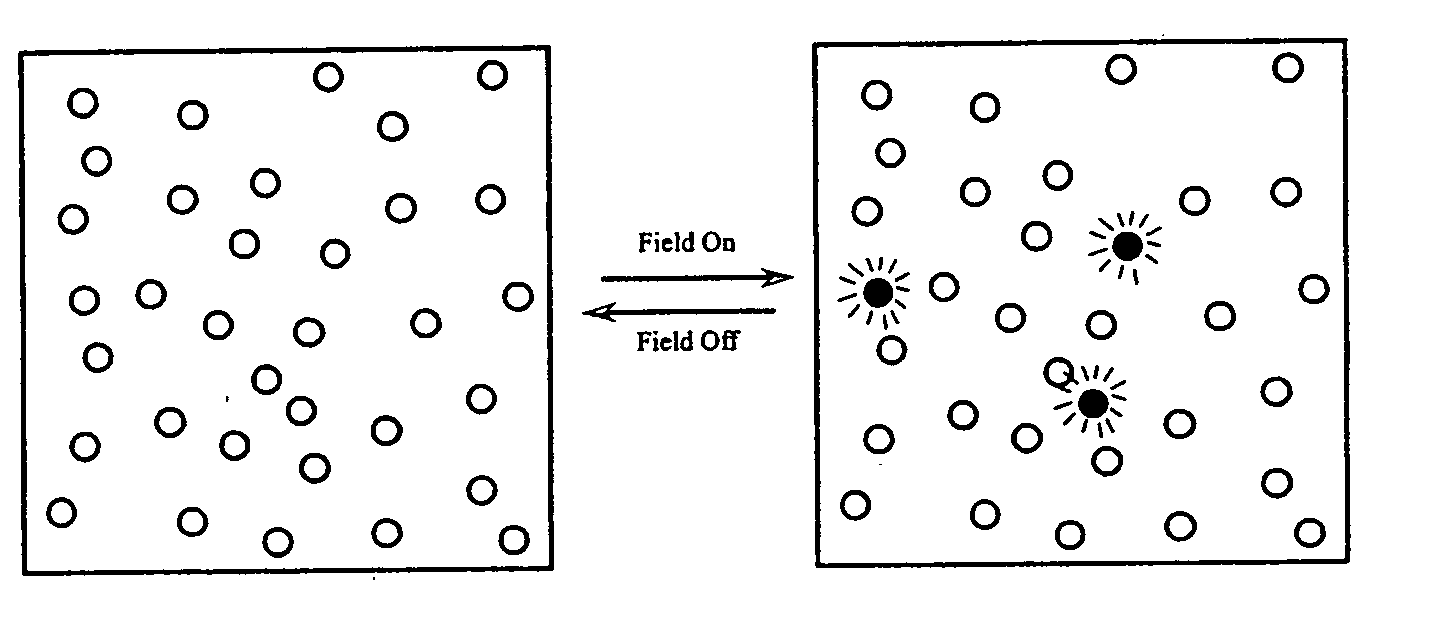
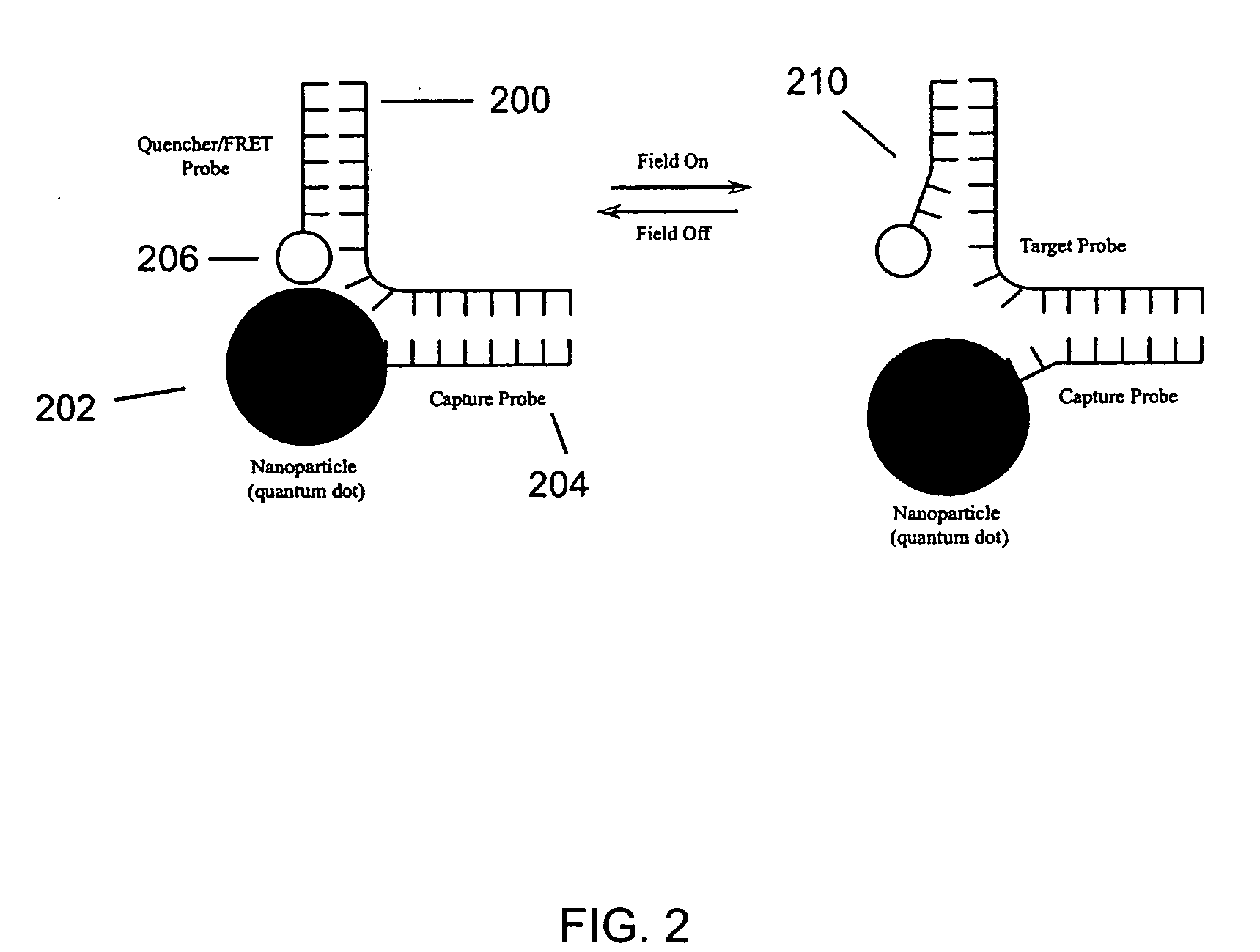
[0165] The ability to produce an oscillatory signal at the nanoscale has two basic components; turning the system off, and turning the system on. For fluorescence resonant energy transfer (FRET) pairs, this could be the transition from red to green emission, with the green emission being “on” as a result of the free energy introduction and the red emission being in the relaxed “off” state. In another embodiment, a fluorescent nanoparticle / quencher system in the “off” state would be dim due to the quenching activity when in close proximity, and bright when in the “on” state. Preferred embodiments of this invention would maximize the signal change between states. Preferred embodiments would also establish a differences in frequency spectrum (with respect to the kinetic relaxation of the system) between specific and nonspecifically bound molecules.

[0166] As shown in FIG. 21, the addition of a complementary, one base mismatch, and two base ...

example 2

Nanoparticle Detection of Nucleic Acids in Complex Samples

[0169] The identification of unamplified nucleic acid targets has been heretofore nearly impossible using existing assay methods. While it is possible to detect very low levels of fluorescence (single molecule fluorophores or individual fluorescent nano / microparticles) there are few if any assay techniques with the requisite speed, specificity, selectivity and sensitivity which allow low copy number DNA / RNA targets to be detected without prior amplification of the target DNA. Furthermore, most fluorescent systems (molecular beacon probes, FRET probes, etc.) are used to detect PCR amplified DNA targets. Thus, there exists a need for methods of detecting limited quantities of a target nucleic acid without the use of PCR prior to detection.

[0170] In one embodiment, methods for identifying a target nucleic acid molecule in a sample are provided. The methods include contacting the target nucleic acid molecule with a first nuclei...


PUM

PropertyMeasurementUnit
Timeaaaaaaaaaa
Temperatureaaaaaaaaaa
Forceaaaaaaaaaa

Abstract

The present invention relates to nanoscale transduction systems that produce reversible signals to facilitate detection. In one respect, the invention relates to the analysis of molecular binding events using higher order signaling nanoscale constructs, or “nanomachines”, that allow nanostructures to be individually detectable, even in the midst of high background noise. Such systems are particularly useful for improving the performance of rare target detection methods, as well as being generally useful in any field in which sensitivity, discrimination and confidence in detection are important.

Description

TECHNICAL FIELD [0001] The present invention relates to nanoscale transduction systems that produce reversible signals to facilitate detection. In one respect, the invention relates to the analysis of molecular binding events using higher order signaling nanoscale constructs, or “nanomachines”, that allow nanostructures to be individually detectable, even in the midst of high background noise. BACKGROUND OF THE INVENTION [0002] The photonics field includes a variety of emerging and converging technologies relating to light emission transmission, reflection, amplification and detection. The ability to harness and generate light and other forms of radiant energy has produced an equally broad variety of instrumentation, such as optical components and instruments, lasers and other light sources, fiber optics, electro-optical devices, and related hardware and electronics. Even with such an array of technologies and instrumentation, advances in photonics are still limited by the ways in w...

Claims


Application Information

Patent Timeline
IPC IPC(8): C12Q1/68G01NG01N33/00G01N33/53G01N33/543H01L21/00
CPCB82Y5/00B82Y10/00G01N33/54346B82Y30/00B82Y15/00
Inventor HELLER, MICHAELSULLIVAN, BENJAMINZLATANOVIC, SANJAESENER, SADIKDEHLINGER, DIETRICH
Owner RGT UNIV OF CALIFORNIA
Why Eureka
Try Eureka