Light emitting display device and driving control method therefor

a technology of display device and driving control method, which is applied in the direction of electric variable regulation, process and machine control, instruments, etc., can solve the problems of reducing the ripple component level in the dc-, the ripple component cannot be too much in comparison with the increasing rate of capacitance, and the ripple component can be more reduced in the dc-. , to achieve the effect of increasing the circuit size and reducing the display quality of images

Inactive Publication Date: 2005-08-18
TOHOKU PIONEER CORP
View PDF7 Cites 13 Cited by
  • Summary
  • Abstract
  • Description
  • Claims
  • Application Information

AI Technical Summary

Benefits of technology

[0032] The present invention has been made, considering the above-described problems, and its object is to provide a light-emitting display device and a driving control method therefor, by which reduction in display quality of images, which is caused by, for example, a ripple component generated in, for example, a power supply circuit represented by the above-described DC-DC converter can be effectively prevented without increasing the circuit size.

Problems solved by technology

Here, the boosting voltage of the DC-DC converter is used as the driving voltage Va supplied to the source of the transistor Tr2 as already explained, and it is unavoidable to some extent that ripple noise (ripple component) is superimposed on the voltage Va, because switching operations are required as an operating principle in this kind of DC-DC converters.
Here, when a smoothing capacitor C1 with large capacitance is used, the level of the ripple component can be more reduced in the DC-DC converter, but the reducing effect of the ripple component cannot be expected too much in comparison with the increasing rate of the capacitance.
Especially, not only the increased cost, but also the larger volume for a capacitor is required in order to use the capacitor for a cellular telephone and a personal digital assistance (PDA), though the demand for the display panel shown in FIG. 1 and the DC-DC converter which drives the panel has been grown as a cellular telephone and PDA have been widely used.
Accordingly, there is a practical limitation in designing the smoothing capacitor with controlled capacitance to some extent.
Thereby, there can be presented a problem that the display quality of images is remarkably reduced, for example, a fine striped pattern, or flickering phenomenon is generated on the display panel.
However, the regulator circuit always causes power loss of (Vin−Vout)×Iout=P[w].
Accordingly, the duration time of a battery is remarkably reduced to cause a state in which it is difficult to adopt the above-described portable equipment.

Method used


Image

  • Light emitting display device and driving control method therefor
  • Light emitting display device and driving control method therefor
  • Light emitting display device and driving control method therefor

Examples


first embodiment

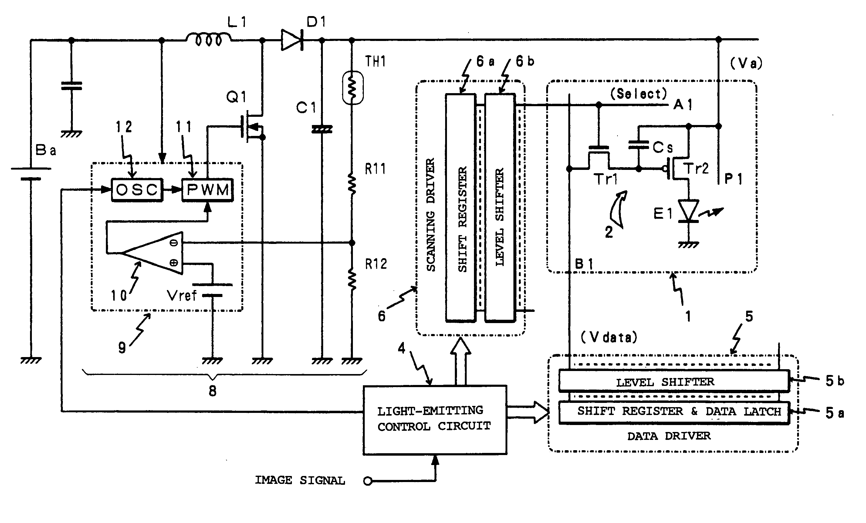
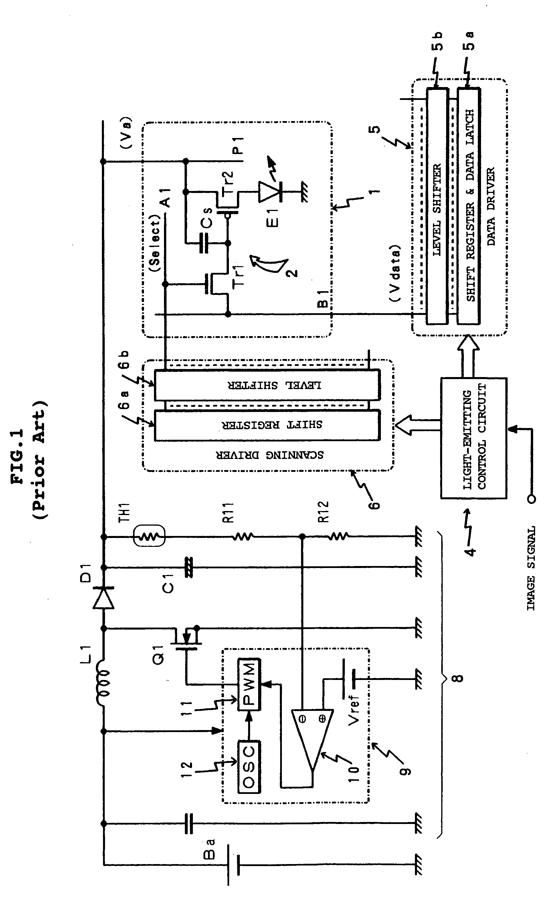
[0045] In the first place, FIG. 6 shows a first embodiment in which a display panel 1 having a pixel configuration according to a conductance controlled method is used as shown in FIGS. 1 and 2. Moreover, in this embodiment, the display panel 1 has a configuration in which the panel 1 is electrically connected to a section of a circuit structure for a switching operation, that is, a DC-DC converter 8, and an operating power source voltage Va is supplied from the DC-DC converter 8 concerned to the panel 1. The configuration of the panel 1 is the same as that shown in the example of FIG. 1 which has been already explained.

[0046] On the other hand, the embodiment shown in FIG. 6 has a configuration in which a switching operation in the DC-DC converter 8 and an operation for scanning selection of scanning lines in the display panel are in synchronization with each other. That is, a clock signal (scanning shift clock) corresponding to a scanning frequency given from a light-emitting cont...

second embodiment

[0058]FIG. 8 shows a second embodiment according to the present invention, and this example shows a pixel configuration in which a lighting driving method for time-shared gradation expression, wherein the driving method is called a simultaneous erasing scan (SES) method, is adopted and three TFTs are included. Here,

[0059]FIG. 8 shows a circuit structure of one display pixel as one representative case on account of limited space, and many circuit structures described above are arranged like a matrix on the display panel 1 shown in FIG. 6.

[0060] The circuit structure of the pixel shown in FIG. 8 comprises an erasing transistor Tr3 using TFTs in addition to the pixel configuration of the lighting driving method called the conductance controlled method which has already been explained, referring to FIGS. 1 and 6. Here, in FIG. 8, components corresponding to those which have been already explained, referring to FIGS. 1 and 6 are denoted by the same reference numerals as those in FIGS. 1...

third embodiment

[0071] Then, FIG. 9 shows a third embodiment according to the present invention in which a switching regulator circuit in a DC-DC converter is improved. Here, in FIG. 9, components corresponding to those in the DC-DC converter 8 which has been already explained, referring to FIGS. 1 and 6, are denoted by the same reference numerals as those in FIGS. 1 and 6. And, an oscillator 12 in the DC-DC converter shown in FIG. 9 comprises a phase locked loop (PLL) circuit.

[0072] The PLL circuit including the oscillator 12 comprises: a phase detector (PD) 12a which outputs an error signal corresponding to a phase difference which is obtained by comparison of the phase between a clock signal from a light-emitting control circuit 4 and the divided output of a divider 12d; a low-pass filter (LPF) 12b which extracts a direct current by receiving the output from the phase detector 12a; a voltage control oscillator (VCO) 12c in which the oscillation frequency is decided by the direct current obtained...


PUM


Abstract

A clock signal in synchronization with a data writing signal, every scanning line, which is supplied from a light-emitting control circuit 4 to a scanning driver 6, is supplied to an oscillator 12 which generates a reference switching signal, according to a PWM method, in a DC-DC converter 8. Thereby, the timing at data writing every scanning line is in synchronization with the phase of a ripple component superimposed on a driving voltage Va from the DC-DC converter 8. Accordingly, a problem that there is caused a state in which light-emitting intensity is different every scanning line can be solved because the same voltage Vgs between a gate and a source is supplied every scanning line to a light-emitting driving transistor Tr2 at any time even if the ripple component by switching of the DC-DC converter is superimposed on the driving voltage Va. Thereby, a problem that the display quality of images is remarkably reduced can be prevented in a light-emitting driving operation of a display panel, wherein the operation has a configuration in which an organic EL element with a light-emitting intensity characteristic of a current dependence type, for example, is used as a pixel.

Description

BACKGROUND OF THE INVENTION [0001] 1. Field of the Invention [0002] The present invention relates to a light-emitting display device provided with a display panel on which active driving of light-emitting elements forming pixels are performed by, for example, thin film transistors (TFTs), and, especially, to a light-emitting display device, and a driving control method therefor, by which deterioration in image quality displayed can be effectively prevented by a ripple component which is superimposed on a driving power of the display panel. [0003] 2. Description of the Related Art [0004] Development of a light-emitting display device using a display panel with a configuration in which light-emitting elements are arranged like a matrix has been widely promoted, and, for example, an organic electroluminescence (EL) element which uses an organic material for a light-emitting layer has received widespread attention as a light-emitting element used for such a display panel. The background...

Claims


Application Information

Patent Timeline
Patent Type & Authority Applications(United States)
IPC IPC(8): G09G3/20H01L51/50G09G3/30G09G3/32H02M3/137H05B33/14H05B44/00
CPCG09G3/3233G09G2300/0842G09G2330/02G09G2320/0233G09G2310/0251
Inventor HAYAFUJI, AKINORIKANAUCHI, KATSUHIRO
Owner TOHOKU PIONEER CORP
Why Eureka
Try Eureka