Method and arrangement for analyzing samples

a sample and sample technology, applied in the field of laser scanning microscopy, can solve the problems of inability to match the emission of a dye to a detection channel, the method of the prior, and the problem becomes more severe, so as to achieve the effect of increasing the quantity of fluorescence dyes to be detected

Inactive Publication Date: 2005-08-18
CARL ZEISS MICROSCOPY GMBH
View PDF6 Cites 67 Cited by
  • Summary
  • Abstract
  • Description
  • Claims
  • Application Information

AI Technical Summary

Benefits of technology

[0030] Dyes with sharply overlapping excitation and emission spectra can hardly be separated from one another without crosstalk. This problem becomes more severe as the quantity of fluorescence dyes to be detected increases. Therefore, a unique correlation of the emission of a dye to a detection channel is impossible. Yet this is absolutely necessary for accurate assessment in the analysis of multiply labeled samples.
[0031] Other troublesome and unwanted effects in multifluorescence recordings are superimposed background signals. These background signals can be reflections of individual lasers at the sample or broadband autofluorescence signals of sample constituents that overlap the spectral signatures of the fluorescence-labeled sample locations to be analyzed and therefore make it difficult and sometimes even impossible to analyze these sample locations.
[0032] Chromosomes that are labeled with up to seven different dyes by means of multicolor banding technique, FISH or related techniques pose special demands for the dete...

Problems solved by technology

Disadvantages of the Methods of the Prior Art
This problem becomes more severe as the quantity of fluorescence dyes to be detected increases.
Therefore, a unique correlation of the emission of a dye to a detection channel is impossible.
Other troublesome and unwanted effects in multifluorescence recordings are superimposed background signals.
These background signals can be reflections of individual lasers at the sample or broadband autofluorescence signals of sample constituents that overlap the spectral signatures of the fluorescence-labeled sample locations to be analyzed and therefore make it difficult and sometimes even impossible to analyze these sample locat...

Method used


Image

  • Method and arrangement for analyzing samples
  • Method and arrangement for analyzing samples
  • Method and arrangement for analyzing samples

Examples


Embodiment Construction

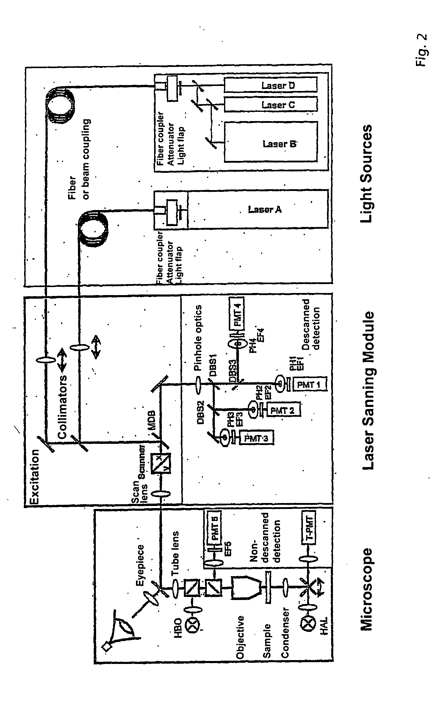
[0065] The background of the method according to the invention is a spectrally split detection of fluorescence. For this purpose, the emission light is split from the excitation light in the scan module or in the microscope (with multiphoton absorption) by means of an element for separating the excitation radiation from the detected radiation such as the main color splitter (main dichroic beam splitter (MDB)) or an AOTF according to DE19859314 A1 or DE 19842288. With transmitted-light arrangements, this type of element can also be entirely omitted. A block diagram of the detector unit to be described in the following is shown in FIG. 4. With confocal detection, the light from the sample L is focused through a diaphragm (pinhole) PH by means of imaging optics PO, so that fluorescence occurring outside of the focus is suppressed. In nondescanned detection, the diaphragm is omitted. The light is now divided into its spectral components by an angle-dispersive element DI. The angle-dispe...


PUM


Abstract

A method and/or arrangement for the analysis of fluorescing samples in an image-generating microscope system, preferably a laser scanning microscope, wherein the sample is scanned point-by-point or line-by-line in at least one surface section and a dispersive splitting of the radiation coming from the sample is carried out during the scanning, wherein the split radiation is detected by at least one line of detector elements in a wavelength-dependent manner, a selection of two-dimensional or three-dimensional sample parts which correspond to pre-stored two-dimensional or three-dimensional geometric objects or the like is carried out based on the recorded and stored intensity distribution of at least one of these detection elements and/or at least one other detection element for the radiation reflected from the sample by image processing, and an analysis of the spectral signature and/or spatial spectral sequence is carried out for at least a portion of these sample regions with respect to the fluorescence markers arranged thereon.

Description

CROSS-REFERENCE TO RELATED APPLICATIONS [0001] This application claims priority of PCT Application Serial No. PCT / EP03 / 05033, filed May 14, 2003 and German Application No. 102 22 779.9, filed May 16, 2002, the complete disclosures of which are hereby incorporated by reference.BACKGROUND OF THE INVENTION [0002] a) Field of the Invention [0003] The invention is directed to a method in fluorescence microscopy, particularly laser scanning microscopy, for analyzing predominantly biological samples, preparations and associated components. Included are methods based on fluorescence detection, e.g., fluorescence correlation microscopy, methods for screening active ingredients (high throughput screening), total internal reflection fluorescence microscopy (TIRF), and nearfield scanning microscopy. [0004] The transition from the detection of a few broad-spectrum dye bands to the simultaneous acquisition of whole spectra opens up new possibilities for the identification, separation and correlat...

Claims


Application Information

Patent Timeline
IPC IPC(8): G01N21/64G02B21/00
CPCG01N21/6428G01N21/6458G02B21/008G02B21/0076G02B21/0064
Inventor GERSTNER, VOLKERLINDENAU, JOERG
Owner CARL ZEISS MICROSCOPY GMBH
Why Eureka
Try Eureka