Radiator and method of manufacturing the same

Active Publication Date: 2005-09-08
NAKAMURA IND MFG CO LTD
View PDF11 Cites 17 Cited by
  • Summary
  • Abstract
  • Description
  • Claims
  • Application Information

AI Technical Summary

Benefits of technology

[0033] Furthermore, the thickness of the heat-radiating fins at a base on the side of the metal plate surface is increased and the distal ends thereof are reduced in thickness by the

Problems solved by technology

However, since the former of the two radiator types is manufactured by extrusion molding or casting, there is a limit to how thin the heat-radiating fins can be made and how many heat-radiating fins can be formed, and it has been difficult to enhance the heat radiation effect.
Therefore, the radiation efficiency is low because the heat from the heating element provided to the back surface of the radiator sometimes does not reach the tongue-shaped fins, and the radiating effects of the tongue-shaped fins cannot be achieved.
Also, copper has a higher coefficient of thermal conductivity than aluminum, and although fashioning radiators from a copper material is inherently desirable, the problem with copper is that it cannot be extrusion-molded as shown in Patent Document 1.
Theref

Method used


Image

  • Radiator and method of manufacturing the same
  • Radiator and method of manufacturing the same
  • Radiator and method of manufacturing the same

Examples


example 1

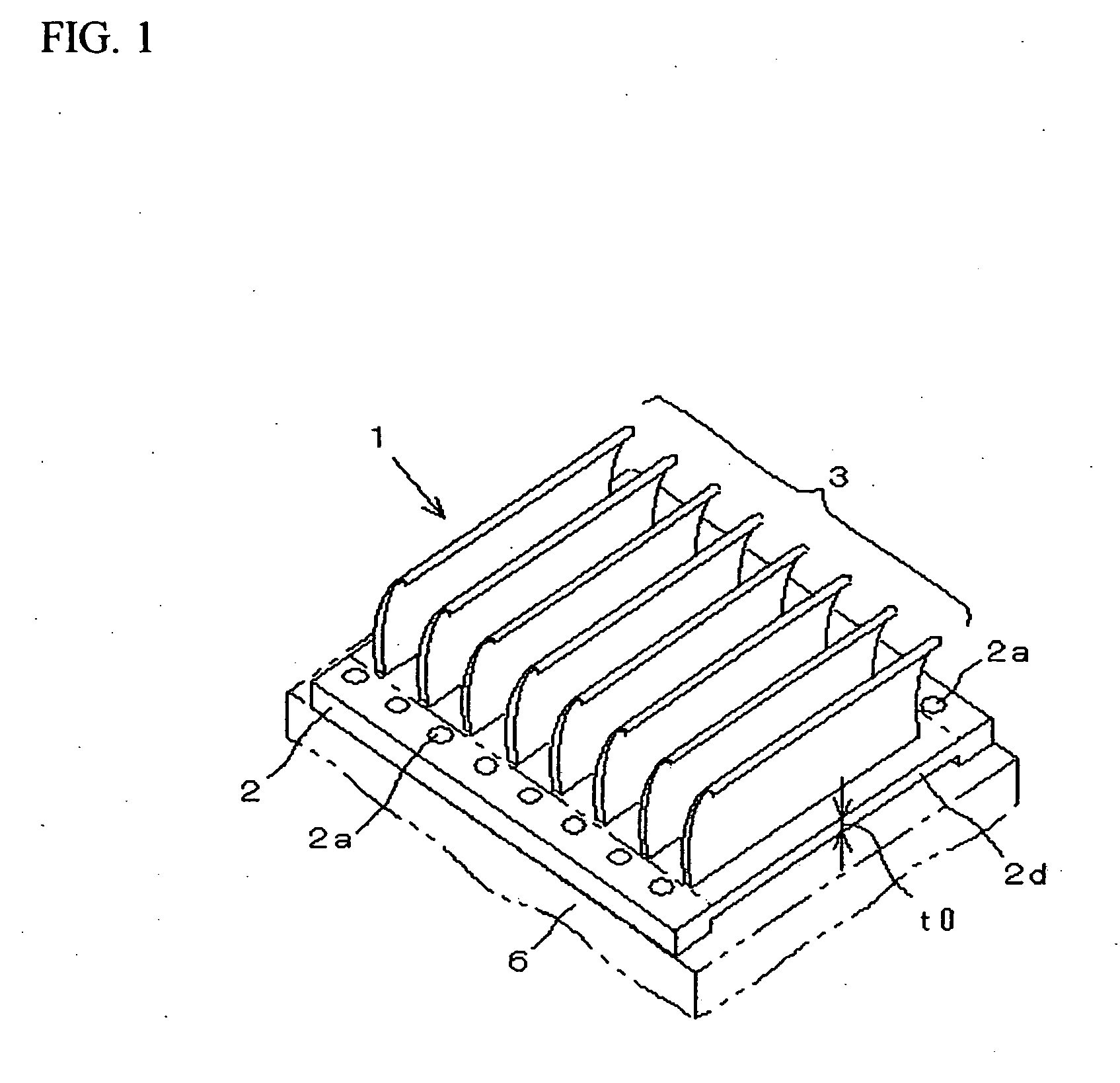
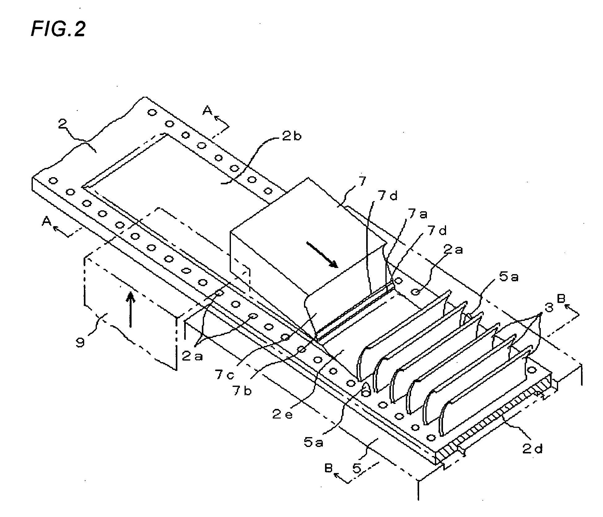
[0056]FIG. 1 is a perspective view depicting a radiator according to Example 1 of the present invention, FIG. 2 is a perspective view depicting a method of manufacturing the radiator of FIG. 1; FIG. 3 is a cross-sectional view depicting the portion that is cut along line A-A of FIG. 2, and FIG. 4 is a cross-sectional view depicting the portion that is cut along line B-B of FIG. 2. The metal material used in the radiator in this example is capable of being subjected to plastic working, and also has a good coefficient of thermal conductivity. For example, a metal plate with a specific plate thickness formed from aluminum, an aluminum alloy, a copper alloy, stainless steel, or another such material can be used.

[0057] The radiator 1 of the present example is configured from a metal plate 2 and a plurality of heat-radiating fins 3 formed integrally on the surface thereof. The heat-radiating fins 3 extend parallel to the narrow side of the metal plate 2. Also, this plurality of heat-radi...

example 2

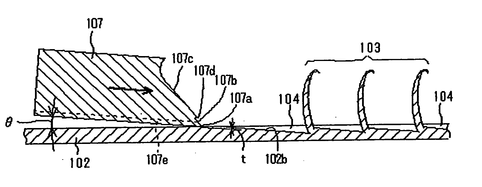
[0075]FIG. 10 depicts the second example of the present invention, and depicts a method of forming the heat-radiating fins with an even greater surface area in the radiator. A carving tool 10 used in this second example is substantially the same as the carving tool 7 used in the first example, but is different in that a plurality of concavities 11 are formed in a blade 10a perpendicular to the direction of movement in the distal end at the bottom surface. This carving tool 10 has two inclined surfaces 10b and 10c that are inclined at specific angles from the blade 10a, and a step 10d is formed between these two inclined surfaces 10b and 10c in the same manner as in the carving tool 7 shown in the first example.

[0076] Similar to the first example previously described, pilot holes 2a that function as positioning and interlocking parts are formed in the hoop-shaped metal plate 2 sequentially supplied from a supply device, a press tool 9 is pressed from the other side of the hoop-shape...

example 3

[0079]FIG. 11 depicts the third example of the present invention, and depicts a method of manufacturing a radiator with a configuration wherein a plurality of heat-radiating fin rows are formed simultaneously in the hoop-shaped metal plate 2. A carving tool 20 used in the third example is also substantially the same as the carving tool 7 used in the first example, but is different in that a pair of blades 22 and 23 are formed by forming a deep dividing groove 21 in the middle of the blade perpendicular to the movement direction at the distal end on the side of the bottom surface to divide the blade in two, as shown in FIG. 11. Also, in the carving tool 20, two pairs of inclined surfaces 22a, 22b and 23a, 23b that are inclined at specific angles from the blades 22 and 23 are formed, and steps 22c and 23c are formed between these two pairs of inclined surfaces 22a, 22b and 23a, 23b.

[0080] Pilot holes 2a that function as positioning and interlocking parts are formed in the hoop-shaped...


PUM

PropertyMeasurementUnit
Lengthaaaaaaaaaa
Thicknessaaaaaaaaaa
Widthaaaaaaaaaa

Abstract

In a method of manufacturing a radiator, the blade of a carving tool is applied at a specific angle to the surface of a metal plate with a high coefficient of thermal conductivity, the carving tool is advanced while the angle is maintained, and the surface of the metal plate is carved out to form plate-shaped heat-radiating fins vertically upward. A radiator is manufactured in which a plurality of heat-radiating fins are integrally formed vertically upward at a specific pitch from a single metal plate by repeating a step in which the carving tool is retracted at a specific pitch, the metal plate is carved out, and a heat-radiating fin is formed. A radiator that has high radiation efficiency and is highly safe during handling can be manufactured at low cost.

Description

BACKGROUND OF THE INVENTION [0001] 1. Technical Field [0002] The present invention relates to a radiator for efficiently dissipating heat produced by semiconductor integrated circuits and other such electronic components, and to a method of manufacturing a radiator for raising up plate-shaped heat-radiating fins from a metal plate and integrally forming a radiator. [0003] 2. Related Art Description [0004] Semiconductor integrated circuits and other such electronic components, which are constantly shrinking in size and increase in density, generate heat during use. Therefore, radiators for radiating heat are attached to packages for accommodating the electronic components. Forced cooling by a cooling fan can also be performed as needed. [0005] Radiators commonly used for heat radiation in semiconductor integrated circuits and other such electronic components have a configuration wherein multiple pectinate heat-radiating fins stand straight up on a base. Bonding the radiator to the pa...

Claims


Application Information

Patent Timeline
IPC IPC(8): B21D53/02H05K7/20B23D3/00B23D13/00B23P15/26F28F3/04H01L23/36
CPCB23P2700/10F28F3/04H01L21/4878Y10T29/4935H01L2924/0002H01L23/3672H01L2924/00B21J5/068
Inventor MIYAHARA, HIDEYUKI
Owner NAKAMURA IND MFG CO LTD
Why Eureka
Try Eureka