Corrosion-resistant clad plate with high bonding strength and fabricating method thereof
- Summary
- Abstract
- Description
- Claims
- Application Information
AI Technical Summary
Benefits of technology
Problems solved by technology
Method used
Image

Examples
example 1
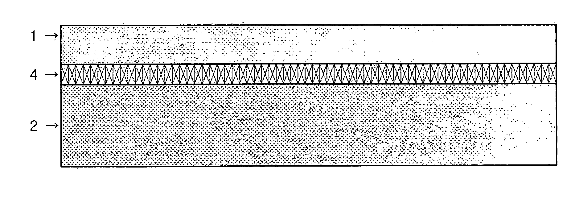
Corrosion-Resistant Clad Plates (or Sheets)
[0070] Since Cu (pure Cu or a Cu-alloy) and Ni (pure Ni or a Ni-alloy) react with Ti to form a low-melting eutectic phase, one of them or a stack of the Cu and Ni sheets was inserted to an interface between the Ti (pure Ti or a Ti-alloy) and the substrate (Fe, a Fe-alloy, Cu, a Cu-alloy, Ni, or a Ni-alloy). Then, by using the resistance seam welding machine, the multi-layered clad plates (or sheets) were fabricated.
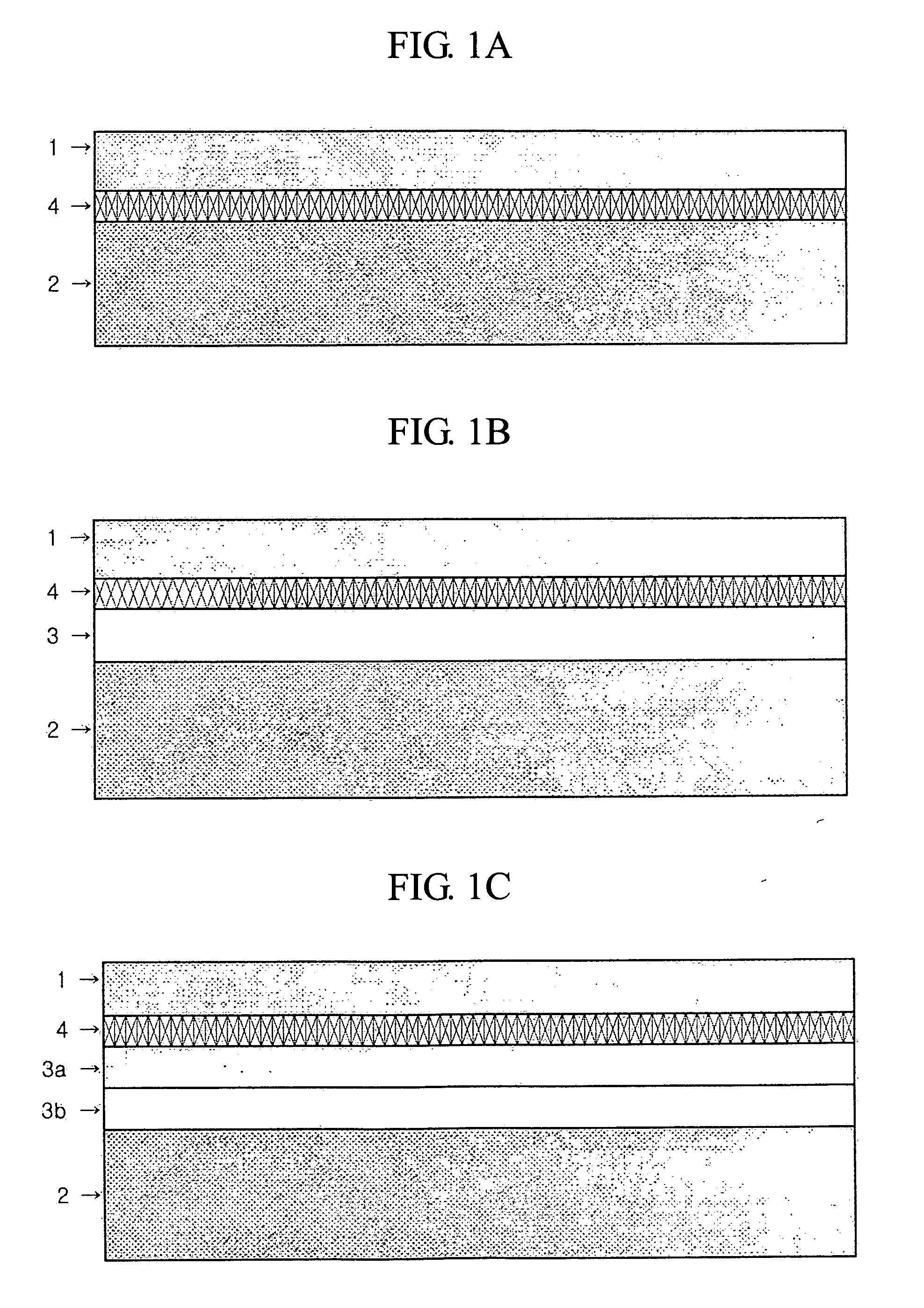
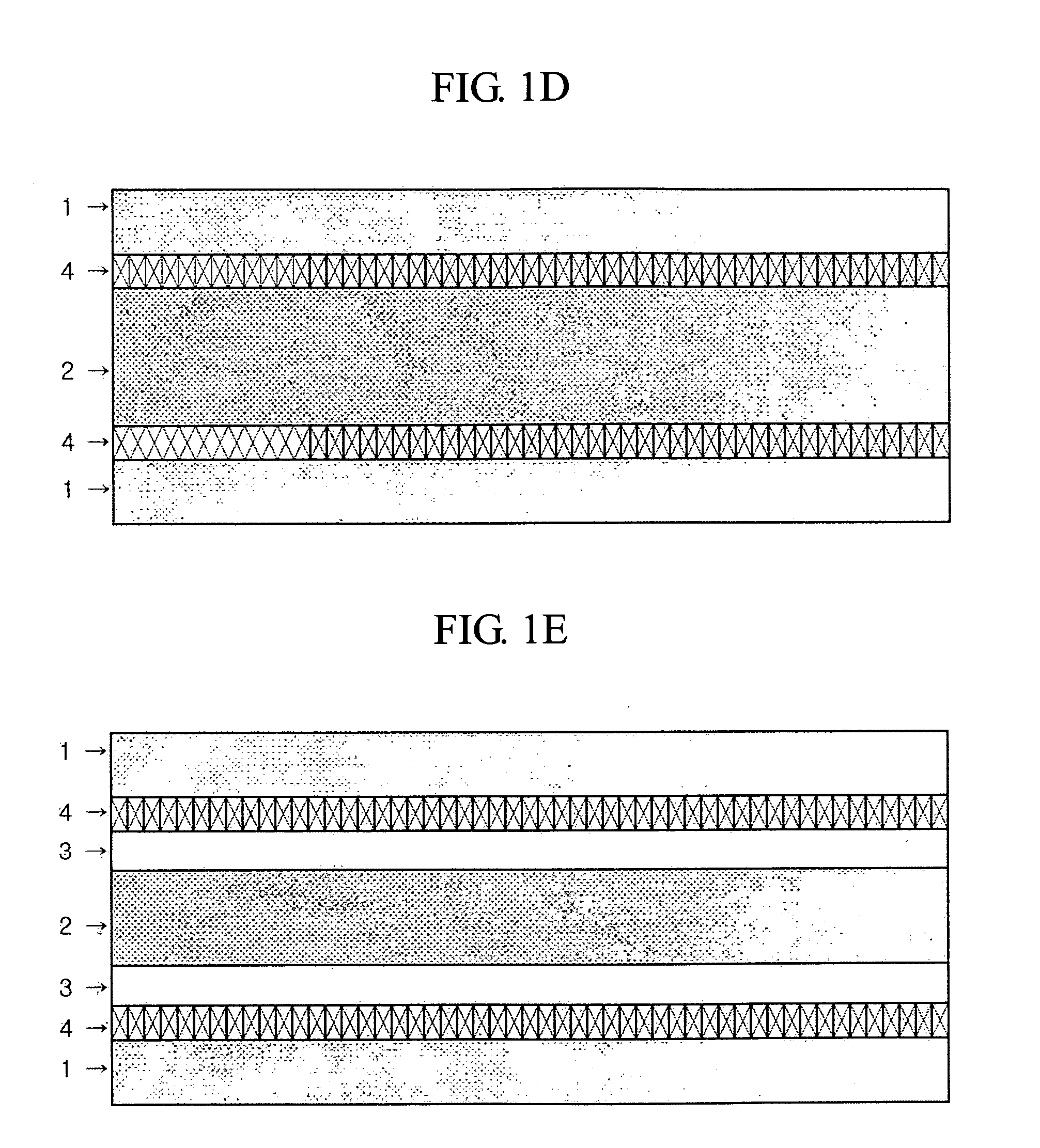
[0071] Thusly fabricated single (one-sided) clad plates (a Ti being claded on one side of a Fe substrate) has a three-layered structure including one insert metal, such as Ti clad layer / Ni insert layer / Fe substrate or Ti clad layer / Cu insert layer / Fe substrate, or a four-layered structure including two insert metals, such as Ti clad layer / Ni insert layer / Cu insert layer / Fe substrate or Ti clad layer / Cu insert layer / Ni insert layer / Fe substrate. In the present example, Ni indicates a Ni pure metal or a Ni-base alloy, and Cu indi...
example 2
Corrosion-Resistant Clad Plates (or Sheets) with Higher Bonding Strength
[0077] Since it has been found from Example 1 that Ni is most preferable as an insert metal for high bonding strength of Ti clad plates, Ni was selected to be inserted to the interface between the Ti (pure Ti or a Ti-alloy) and the substrate (Fe, a Fe-alloy, Cu, a Cu-alloy, Ni, or a Ni-alloy). Then, by using the resistance seam welding, the multi-layered clad plates (or sheets) were fabricated. The processing factors are as follows: applied electric current was 5-50 kA, applied pressure was 1-200 MPa, welding time was 0.001-1 sec, cooling time was 0.001-1 sec, and welding speed was 500-10000 mm / min. In the present Example, the welding time and the cooling time were limited to less than 1 sec, so that the brittle intermetallic compounds may not be generated at the interface of the clad metal and the substrate or the clad metal and the insert metal.
[0078] Thusly fabricated clad plates has a structure of Ti / eutec...
PUM
| Property | Measurement | Unit |
|---|---|---|
| Time | aaaaa | aaaaa |
| Time | aaaaa | aaaaa |
| Pressure | aaaaa | aaaaa |
Abstract
Description
Claims
Application Information
 - Generate Ideas
- Intellectual Property
- Life Sciences
- Materials
- Tech Scout
- Unparalleled Data Quality
- Higher Quality Content
- 60% Fewer Hallucinations
Browse by: Latest US Patents, China's latest patents, Technical Efficacy Thesaurus, Application Domain, Technology Topic, Popular Technical Reports.
© 2025 PatSnap. All rights reserved.Legal|Privacy policy|Modern Slavery Act Transparency Statement|Sitemap|About US| Contact US: help@patsnap.com