Chip resistor having low resistance and its producing method

a technology of resistors and chips, applied in the field of chip resistors, can solve the problems of increasing the temperature coefficient of resistance increasing the thickness of the resistor element, and increasing the weight so as to reduce the thickness of the connection terminal electrode, and reduce the height of the chip resistor.

Active Publication Date: 2005-09-15
ROHM CO LTD
View PDF3 Cites 23 Cited by
  • Summary
  • Abstract
  • Description
  • Claims
  • Application Information

AI Technical Summary

Benefits of technology

[0028] As described above, a resistor element formed of an alloy of high-resistant metal and low-resistant metal into a rectangular solid includes a surface formed with a plating layer which is made of pure metal with resistance lower than the alloy making the resistor element. Due to this arrangement, the resistance between the connection terminal electrodes is lowered by the pure metal plating layer which is formed on the alloy resistor element. Thus, the resistance between the connection terminal electrodes, which is resistance of the chip resistor, can be lowered without increasing the percentage 5 of the low-resistant metal relative to the high-resistant metal in the alloy making the resistor element, and also without increasing the thickness of the resistor element. As resistance of a chip resistor with a predetermined length and width can be lowered without increasing the percentage of the low-resistant metal, hence without making its purity closer to low-resistant metal (base material metal), the above-described temperature coefficient of resistance is not increased. Further, as the thickness of the resistor element is not increased, the above structure reliably prevents difficulty in adjusting resistance by trimming and in bending process of the connection terminal electrodes, as well as increase in weight.
[0040] According to the method of claim 20, a plurality of chip resistors are simultaneously made by using a single lead frame, which contributes to further reduction in production cost.

Problems solved by technology

Unfavorably, this results in a higher temperature coefficient of resistance in the chip resistor.
When the option (2) is taken to reduce the resistance of the chip resistor, the thickness of the resistor element increases, whereby the weight of the chip resistor becomes greater, and it becomes difficult to bend the lengthwise-spaced ends of the resistor element into connection terminals.
Additionally, it becomes significantly difficult to perform trimming adjustment by making a trimming groove in the resistor element for adjustment of the resistance.
When an alloy with such negative temperature coefficient of resistance is used to make a resistor element, unfavorably the negative temperature coefficient of resistance appears as a minus temperature coefficient of resistance of the chip resistor.
Unfavorably, this structure increases the entire height and the weight of the chip resistor.

Method used


Image

  • Chip resistor having low resistance and its producing method
  • Chip resistor having low resistance and its producing method
  • Chip resistor having low resistance and its producing method

Examples


first embodiment

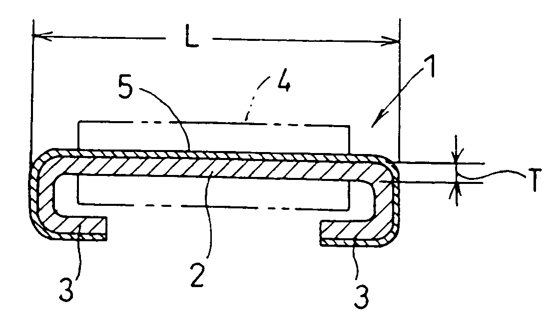
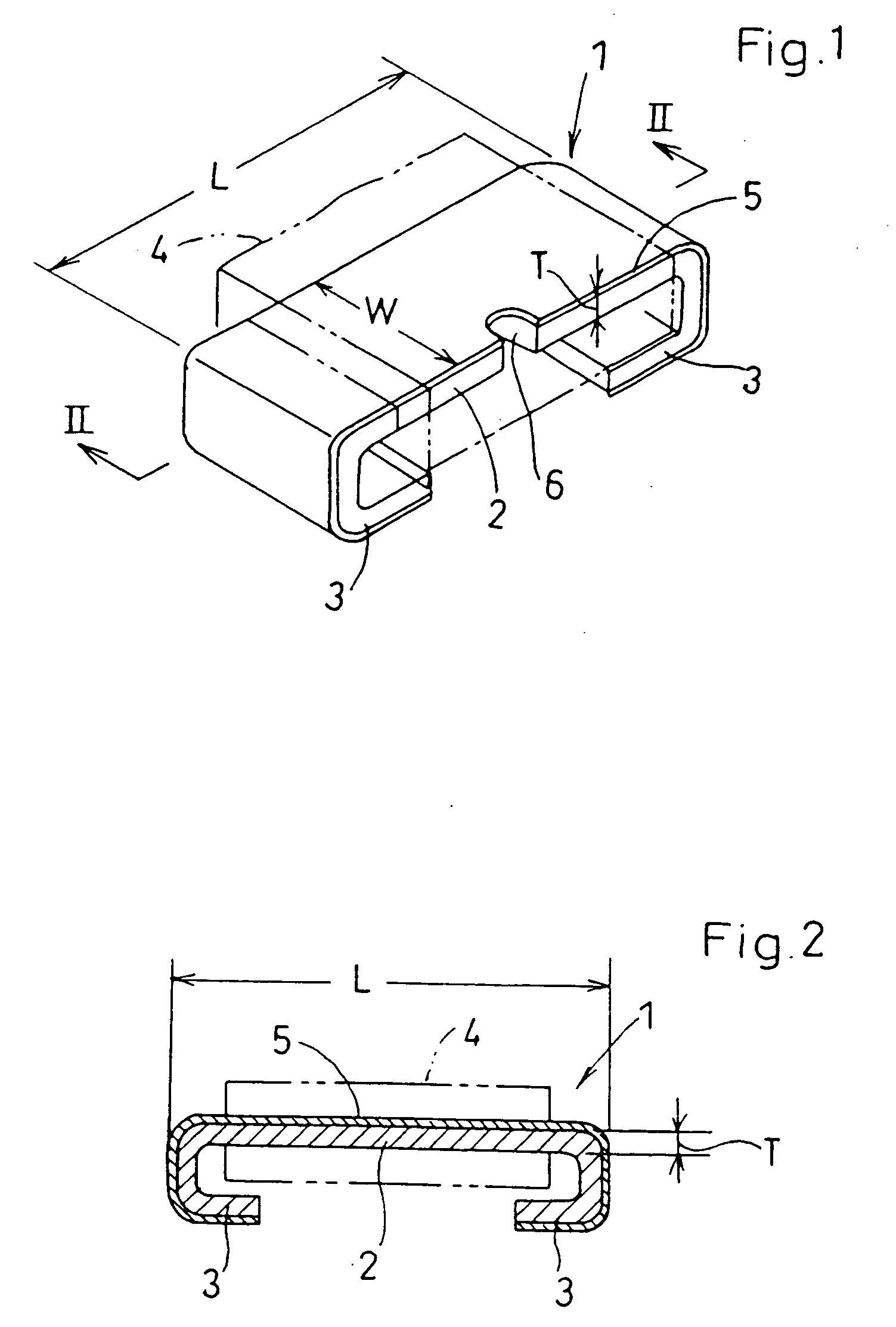
[0071]FIGS. 1-2 illustrate a chip resistor according to a

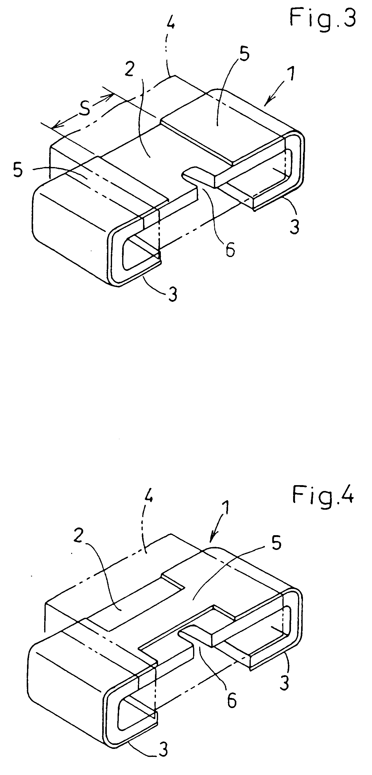
[0072] The chip resistor 1 includes a resistor element 2 which is a rectangular solid having a length L, width W, and a thickness T, a pair of connection terminal electrodes 3 which are integrally formed with the resistor element 2 at both ends of the resistor element 2, each electrode being bent toward the lower surface of the resistor element 2, and an insulator 4 made of heat-resistant synthetic resin or glass for covering the resistor element 2.

[0073] The resistor element 2 and the terminal electrodes 3 are made of an alloy of a metal with low resistance (hereinafter referred to as low-resistant metal) and a metal with high resistance (hereinafter referred to as high-resistant metal), such as copper-nickel alloy, nickel-chrome alloy, or iron-chrome alloy.

[0074] As readily understood, one or both of such low-resistant metal and high-resistant metal may be replaced by an alloy of a low-resistant metal and a high-resistant ...

second embodiment

[0087]FIGS. 12-13 illustrates a chip resistor 11 according to the present invention.

[0088] The chip resistor 11 includes a resistor element 12 which is a rectangular solid having a length L, width W, and a thickness T, a pair of connection terminal electrodes 13 fixed to the ends of the lower surface of the resistor element 12, and an insulator 14 for covering the resistor element 12.

[0089] Similarly to the first embodiment, the resistor element 12 is made of an alloy composed of a low resistance (hereinafter referred to as low-resistant metal) and a metal with high resistance (hereinafter referred to as high-resistant metal) such as copper-nickel alloy, nickel-chrome alloy, or iron-chrome alloy.

[0090] On the other hand, the terminal electrodes 13 are made of an alloy with resistance lower than that of the alloy making the resistor element 12, or of a pure metal such as copper.

[0091] The surface of the resistor element 2 is formed with a plating layer 15 which is made of a pure m...

third embodiment

[0101] the present invention is described below referring to FIGS. 20-26. FIG. 20 illustrates a resistor element 22 which is a rectangular solid having a length L, width W, and thickness T. The resistor element 22 is made of an alloy composed of a metal with low resistance (hereinafter referred to as low-resistant metal) and a metal with high resistance (hereinafter referred to as high-resistant metal), such as copper-nickel alloy, nickel-chrome alloy, or iron-chrome alloy, for example. A metal plate with a thickness T made of such alloy is formed into a rectangle having a length L and a width W.

[0102] The resistor element 22 is formed with a plating layer 25 which is made of a pure metal such as copper or silver with resistance lower than that of the alloy making the resistor element 22. Similarly to the first embodiment, the resistance between connection terminal electrodes 23, 23′ is lowered by the pure metal plating layer 25 which is formed on the alloy resistor element 2. Thus,...


PUM


Abstract

A chip resistor includes a resistor element of a rectangular solid made of an alloy composed of high-resistant metal and low-resistant metal, while also including connection terminal electrodes disposed at the ends of the resistor element that are spaced longitudinally of the rectangular solid. The resistance of the chip resistor is expected to be lowered without incurring an increase in the temperature coefficient of resistance and the weight. The above object is attained by forming a plating layer on the resistor element, where the plating layer is made of pure metal having a lower resistance than that of the alloy constituting the resistor element.

Description

BACKGROUND OF THE INVENTION [0001] The present invention relates to a chip resistor having low resistance of no greater than e.g. 10, and also relates to a method of making the same. [0002] In a conventional chip resistor of the above-mentioned type, as disclosed in JP-A-2001-118701 for example, the resistor element is formed of an alloy into a rectangular solid, the alloy being composed of a base material metal, such as copper, having low resistance (hereinafter referred to as low-resistant metal) and a metal having high resistance (hereinafter referred to as high-resistant metal), such as nickel, which is greater than that of the base material metal. In the resistor element, the rectangular solid has ends provided with connection terminal electrodes to be connected to a printed circuit board or the like by soldering, for example. [0003] The resistance between the connection terminal electrodes of such a chip resistor largely depends on the resistivity of the alloy making the resis...

Claims


Application Information

Patent Timeline
Patent Type & Authority Applications(United States)
IPC IPC(8): H01C7/06H01C17/00H01C17/28
CPCH01C7/06H01C17/28H01C17/006
Inventor TSUKADA, TORAYUKI
Owner ROHM CO LTD
Why Eureka
Try Eureka