Optical sampling interface system for in-vivo measurement of tissue

a tissue and optical sampling technology, applied in the field of optical sampling interface systems, can solve the problems of the degree of optical sampling reproducibility, the abnormal production and use of insulin, and the leading cause of death and disability worldwide, and achieve the effect of reducing sampling variation and/or state fluctuations, and increasing precision and accuracy

Inactive Publication Date: 2005-09-15
GLT ACQUISITION
View PDF99 Cites 15 Cited by
  • Summary
  • Abstract
  • Description
  • Claims
  • Application Information

AI Technical Summary

Benefits of technology

[0054] The invention provides an optical sampling interface system that minimizes sampling variation and/or state fluctuations at a measurement

Problems solved by technology

However, there are many demanding in-vivo applications that cannot be performed in a laboratory setting, but yet require a high degree of optical sampling reproducibility.
Diabetes is a chronic disease that results in abnormal production and use of insulin, a hormone that facilitates glucose uptake into cells.
Diabetes is a leading cause of death and disability worldwide.
To date, no noninvasive techniques for the self-monitoring of blood glucose concentration have been certified by the U.S. Food and Drug Administration.
In all of these studies, diverse limitations were cited that affect the acceptance of such a method as a commercial product.
Fundamental to all the studies is the problem of the small signal attributable to glucose, particularly in view of the difficulty in obtaining a reproducible sample of a given tissue volume, as a result of the complex and dynamic nature of the tissue.
The sampling problem is further accentuated by noting that the reported studies were performed under highly controlled conditions using skilled professionals rather than in a home environment by the consumer.
The measurement is further complicated by the heterogeneity of the sample, the multi-layered structure of the skin, the rapid variation related to hydration levels, changes in the volume fraction of blood in the tissue, hormonal stimulation, temperature fluctuations, and changes in blood constituent concentrations.
However, variations in the physiological state and fluid distribution of tissue profoundly affect the optical properties of tissue layers and compartments over a relatively short period of time.
As a result, relatively small changes in concentration of impermeable solutes in the extracellular fluid, such as glucose, can cause tremendous changes in cell volume.
As herein described, the heterogeneous and dynamic nature of living human skin leads to sampling uncertainty in the in-vivo measurement.
Variation in the repeated placement of the optical probe used for sampling at the measuring surface site can lead to sampling errors in two separate ways.
First, variations in the location of the probe can cause a different tissue volume to be sampled and, second, varying the amount of pressure applied by the probe on the tissue can alter the o

Method used


Image

  • Optical sampling interface system for in-vivo measurement of tissue
  • Optical sampling interface system for in-vivo measurement of tissue
  • Optical sampling interface system for in-vivo measurement of tissue

Examples


example i

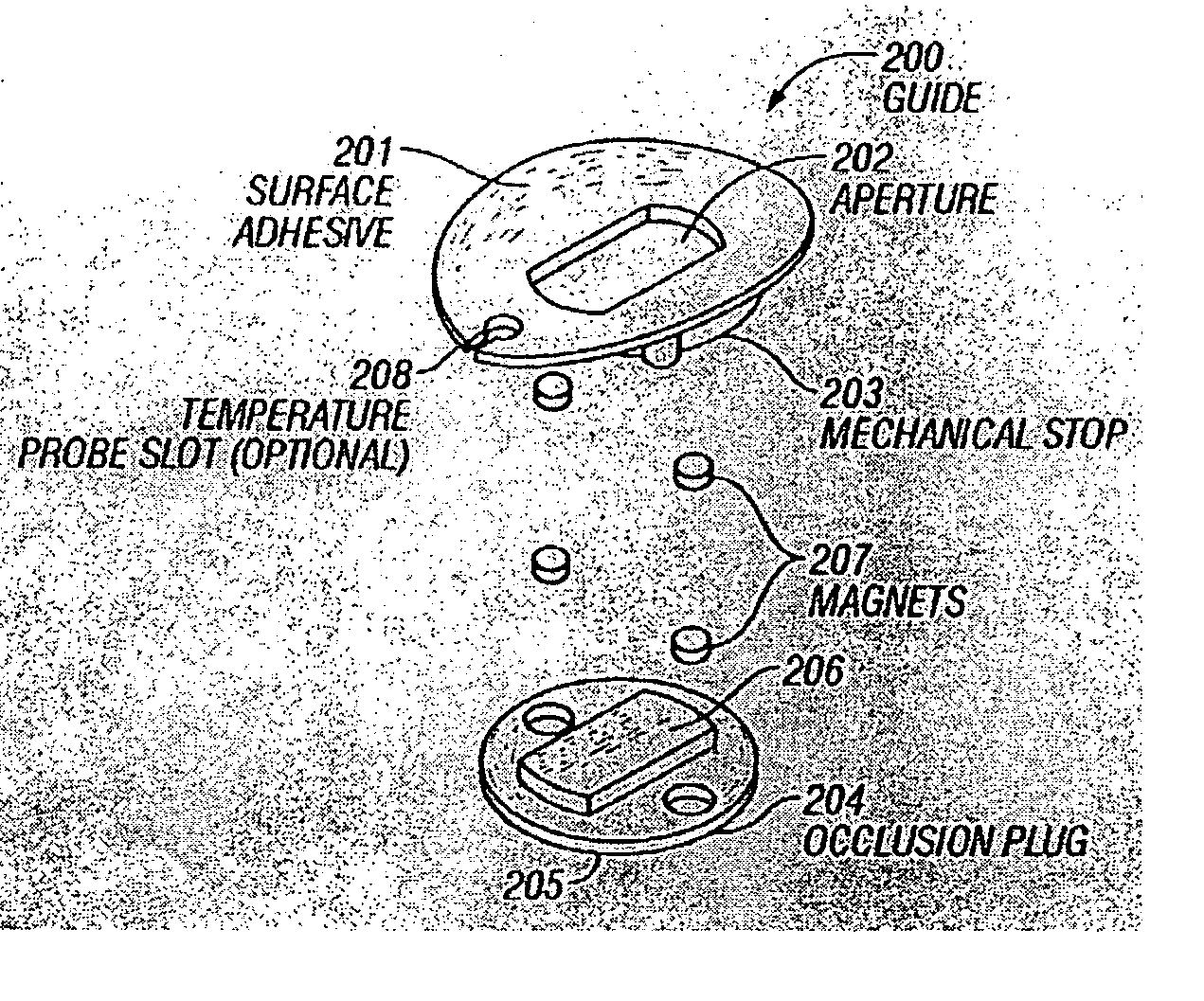
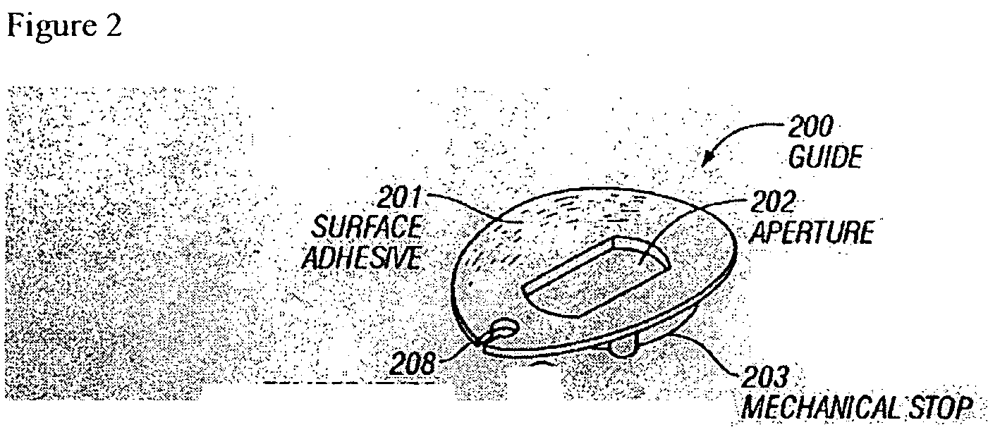
[0144] Referring now to FIG. 9, a guide 200 with a first alignment piece 801 and a separate second alignment piece 802 is presented. In this example, the first alignment piece contains an optional magnet 901 that registers at least the x-, y-, and z-position of the sample probe. The second alignment piece also contains an optional magnet 902 and is used to register at least the y- and z-position of the sample probe. Together the first and second alignment pieces 801, 802 control the rotation of the corresponding sample probe relative to the guide and hence control the position of the sample probe relative to the sample tissue.

[0145] The first and second alignment pieces 801, 802 are optionally attached directly to a tissue sample site or a region about the sample site, as described supra. In another instance, one or more intermediate layers are placed between the first and second alignment pieces 801, 802 and the tissue sample.

[0146] Referring now to FIG. 10, a first layer 1001 is...

example ii

[0152] Referring now to FIG. 13, a guide 200 comprised of two separate alignment pieces 801, 802 is presented. In this example, each of the two alignment pieces contains wings 1301. The wings are attached to the alignment pieces with a flexible material 1302, such as a living hinge. The living hinge compensates for changes in at least one of shape, weight, and applied pressure. In this example, means for alignment of at least one of an x-position, y-position, z-position, and rotational position are provided jointly by the two alignment pieces and / or separately be each of the alignment pieces.

Z-Axis Movable Guide

[0153] In an additional embodiment, rotation of the sample probe is controlled by the guide while allowing z-axis movement of the guide.

[0154] Referring now to FIGS. 14a and 14b, a schematic presentation of sample probe control and sample probe movement relative to a sample is presented. The sample module 103 includes a sample probe 1403. A controller 1401 controls an act...

example 1

[0201] A study was performed to examine the difference in spectral variation between several different near-infrared sampling treatments on a single subject. Near-infrared spectra were collected using a custom built scanning near-infrared spectrometer that collected intensity spectra in diffuse reflectance over the wavelength range 1100-1950 nm. The spectral sampling interval was one nanometer and the signal-to-noise ratio at the peak intensity was approximately 90 dB. The detector used in the study was Indium-Gallium-Arsenide (InGaAs) and the optical configuration consisted of a simple fiber optic interface to the skin with a small (<2 mm) distance between the illumination and detection fibers. Reference spectra were recorded before each sample measurement by scanning a 99% SPECTRALON reflectance material provided by LABSPHERE of North Sutton, N.H. The absorbance spectrum was calculated through Equation (2), supra.

[0202] Approximately twenty near-infrared absorbance spectra were c...


PUM


Abstract

An optical sampling interface system is disclosed that minimizes and compensates for errors that result from sampling variations and measurement site state fluctuations. Embodiments of the invention use a guide that does at least one of, induce the formation of a tissue meniscus, minimize interference due to surface irregularities, control variation in the volume of tissue sampled, use a two-part guide system, use a guide that controls rotation of a sample probe and allows z-axis movement of the probe, use a separate base module and sample module in conjunction with a guide, and use a guide that controls rotation. Optional components include an occlusive element and a coupling fluid.

Description

CROSS REFERENCE TO RELATED APPLICATION [0001] This application claims priority from: [0002] U.S. patent application Ser. No. 10 / 170,921, filed Jun. 12, 2002, which is a continuation-in-part of U.S. patent application Ser. No. 09 / 563,782, filed on May 2, 2000 now U.S. Pat. No. 6,415,167 (Jul. 2, 2002), which is herein incorporated in its entirety by this reference thereto; and [0003] U.S. patent application Ser. No. 10 / 472,856, filed Mar. 7, 2003, which claims priority from PCT Application No. PCT / US03 / 07065, filed Mar. 7, 2003, which claims benefit of U.S. Provisional Patent Application Ser. No. 60 / 362,885, filed Mar. 8, 2002, each of which is herein incorporated in its entirety by this reference thereto.BACKGROUND OF THE INVENTION [0004] 1. Technical Field [0005] The invention relates to optical sampling of tissue in-vivo. More particularly, the invention relates to an optical sampling interface system that includes an optical probe placement guide, a means for stabilizing the samp...

Claims


Application Information

Patent Timeline
IPC IPC(8): A61B5/00G01N21/35
CPCA61B5/14532A61B5/1455G01N21/359A61B5/6833A61B5/1495
Inventor BLANK, THOMAS B.ACOSTA, GEORGEMATTU, MUTUAMAKAREWICZ, MARCYMONFRE, STEPHEN L.LORENZ, ALEXANDER D.RUCHTI, TIMOTHY L.HAZEN, KEVIN H.BERRY, DONOVAN D.ABUL-HAJ, ROXANNE E.
Owner GLT ACQUISITION
Why Eureka
Try Eureka