
Device for applying and monitoring medical rotablation

a technology for applied in the field of executing and monitoring rotaviruses, can solve the problems of significant risk for patients, difficult purely angiographical assessment of the seriousness of calcification, and difficulty in determining the position of calcium in the plaque (surface vs. deep), and achieve the effect of reducing the radiation applied to x-rays

Inactive Publication Date: 2005-09-15
SIEMENS AG
View PDF15 Cites 100 Cited by
  • Summary
  • Abstract
  • Description
  • Claims
  • Application Information

AI Technical Summary

Benefits of technology

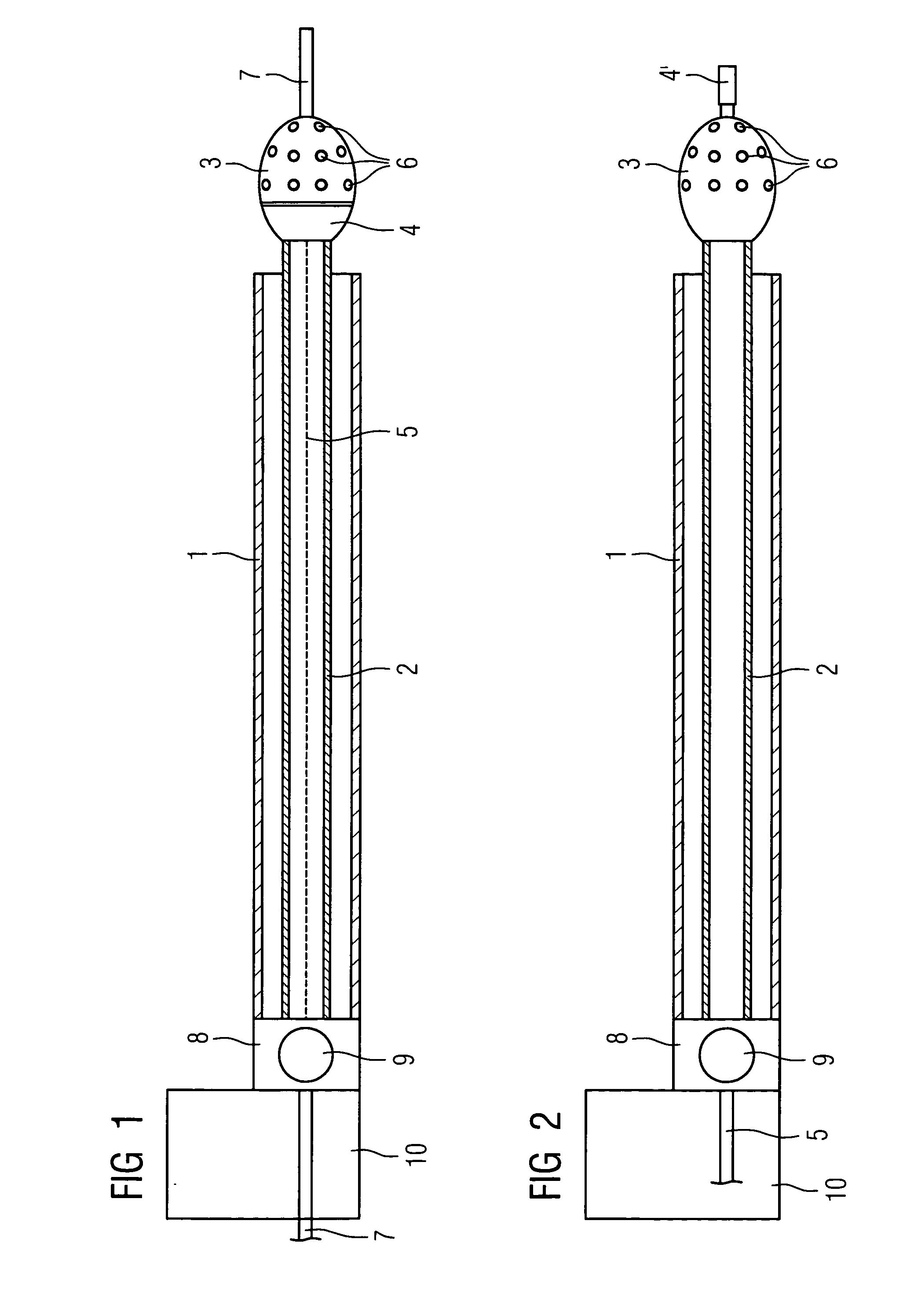
[0014] An object of the invention is thus to create a device for simplified execution and monitoring of rotablation, in which, without changing catheters, a precise observation of the target area is possible simultaneously with the intervention at the plaque.
[0016] The inventive combination of an IVUS catheter with a rotablation angioplasty catheter into an integrated unit produces an optimal system for “debulking” coronary arteries. The major advantage of this solution lies in the reduction both of procedural steps and also of the catheters used, as well as in the reduction of the X-ray radiation applied. The images of the IVUS system supply important additional medical information about the plaque and the artery wall, e.g. anti-inflammatory processes. This enables the “blocked” artery section to be better recognized in each case and the removal of the plaque to be checked during and after the procedure.

Problems solved by technology

The disadvantage of this method is that the coronary arteries are only shown in two dimensions and only the actual narrowing is shown in the X-ray image.
The medical personnel can barely distinguish between plaque and vessel wall during the intervention.
The purely angiographical assessment of the seriousness of the calcification and especially the position of the calcium in the plaque (surface vs. deep) is difficult.
This involves a significant risk for the patient, either too little plaque is removed and the desired blood flow is not restored or the risk of a restenosis remains, or too much tissue is removed and a perforation of the vessel can occur.
The disadvantage of this method is that the entire rotablation arrangement must be removed from the vessel each time.
The disadvantage of this solution lies in the double-lumen catheter, of which the diameter must be significantly larger than a catheter normally used and is thus only ill-suited to introduction into coronary arteries.
The further disadvantage of this solution lies in the increased stiffness of the catheter resulting from the double lumen required, which makes navigating the catheter in the coronary arteries more difficult.
A further disadvantage of this solution lies in the decentralized position of the introduced IVUS probe in relation to the drill head of the rotablator.

Method used


Image

  • Device for applying and monitoring medical rotablation
  • Device for applying and monitoring medical rotablation

Examples


Embodiment Construction

[0023] The combined IVUS rotablation catheter shown in FIG. 1 comprises a catheter sheath 1, in which a hollow flexible drive shaft 2 is arranged which is used both to drive the drill head 3 and also to drive the IVUS sensor 4 arranged in its rear section. 5 indicates a glass fiber line forming the signal line to the IVUS sensor 4. The drill head 3 is equipped in the front section with grinding and cutting particles 6 which are embodied so that, as they rotate, they push aside normal vessel tissue and only remove plaque adhering to the inner wall of the vessel. 7 indicates a guide wire which runs through the catheter but for reasons of clarity the middle of said guide wire is not shown which is initially introduced into the vessel to be treated up to the target area before the combination catheter is introduced. Subsequently the inventive combination IVUS rotablation catheter is pushed onto the guide wire and advanced to the target area. Both the guide wire 7 and also the drill head...


PUM


Abstract

Arrangement for executing and monitoring rotablation, in which a rotating drill head arranged at the tip of a catheter removes plaque adhering to a vessel wall while pushing aside normal vessel tissue, with a rotablation catheter and an IVUS catheter being integrated into one constructional unit.

Description

CROSS REFERENCE TO RELATED APPLICATIONS [0001] This application claims priority to the German application No. 10 2004 008 368.1, filed Feb. 20, 2004 which is incorporated by reference herein in its entirety. FIELD OF INVENTION [0002] The invention relates to a device for executing and monitoring rotablation, in which a rotating drill head arranged at the tip of a catheter removes plaque attached to the vessel wall while pushing aside normal tissue. BACKGROUND OF INVENTION [0003] One of the most frequent diseases in the world with fatal consequences is vascular artery disease, especially a heart attack. This is caused by arthoscelerosis. In such cases build-ups (atherosclerotic plaque) result in a “blockage of the coronary arteries. When coronary angiography shows major narrowing (stenoses) in the coronary blood vessel which cause angina pectoris, restrict capabilities and / or threaten the patient, then currently in the majority of cases a PTCA (Percutaneous transluminal coronary angi...

Claims


Application Information

Patent Timeline
IPC IPC(8): A61B17/00A61B8/00A61B8/12A61B8/14A61B17/14A61B17/22A61B17/32A61B19/00A61M25/00A61M25/16
CPCA61B17/320758A61B2019/528A61B2017/320004A61B2090/3784
Inventor MASCHKE, MICHAEL
Owner SIEMENS AG
Learn More