Apparatus for determining the access time and/or the minimally allowable cycle time of a memory

a technology of access time and/or cycle time, which is applied in the direction of instruments, coding, code conversion, etc., can solve the problems of inability to control the minimumly allowable cycle time characterization at high frequencies, and inability to meet the requirements of a minimumly allowable cycle time characterization. to achieve the effect of facilitating the measurement of the maximum tim

Active Publication Date: 2005-09-15
INFINEON TECH AG INFINEON
View PDF10 Cites 22 Cited by
  • Summary
  • Abstract
  • Description
  • Claims
  • Application Information

AI Technical Summary

Benefits of technology

[0041] In accordance with one embodiment of the present invention, an apparatus, which facilitates the measurement of the maximum time with which signals propagate through a block embedded in an integrated circuit chip and/or of the maximum operating frequency of this block, comprises a clock, a signal generator, programmable delay means, sample-and-hold-means, a comparator and a test status generator.
[0042] The clock produces a timing signal. The signal generator generates signals in response to the timing signal. The signals generated by the signal generator feed input terminals of the block. The programmable delay means generate a delayed timing signal by delaying the timing signal for a programmed delay. The sample-and-hold means sample the output signals of the block in response to the delayed timing signal. The comparator compares the sampled output signals to reference values. The test status generator generates a test status, wherein the test status depends on the results of more than one of the comparisons undertaken by the comparator. As explained above, the test status on th

Problems solved by technology

These very demanding requirements are impossible to meet if the highly sensitive signals generated or to be measured have to cross the interface between the chip and the tester.
Furthermore, the minimally allowable cycle time characterization also requires high frequencies.
Since common embedded memories have hundreds of input and output signals, such as addresses, data inputs and outputs, controlling them by an external tester at high frequencies is not feasible.
For a 1 Mbit memory, the access time of the memory is thus the worst access time over more than on

Method used


Image

  • Apparatus for determining the access time and/or the minimally allowable cycle time of a memory
  • Apparatus for determining the access time and/or the minimally allowable cycle time of a memory
  • Apparatus for determining the access time and/or the minimally allowable cycle time of a memory

Examples


Embodiment Construction

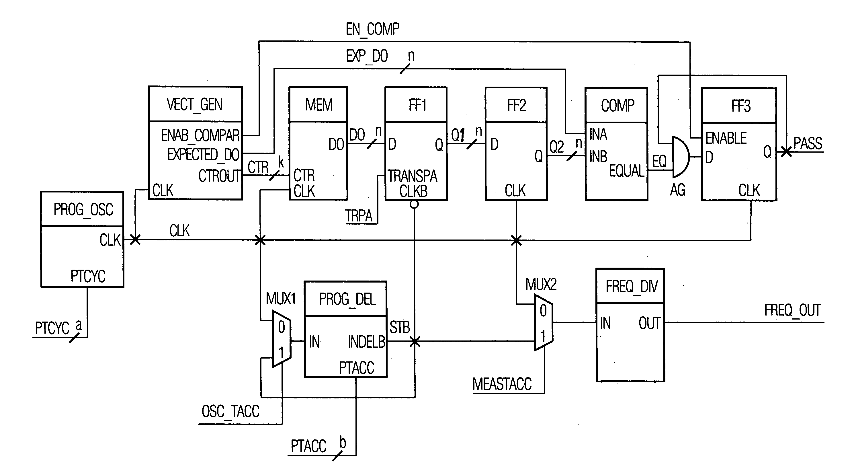
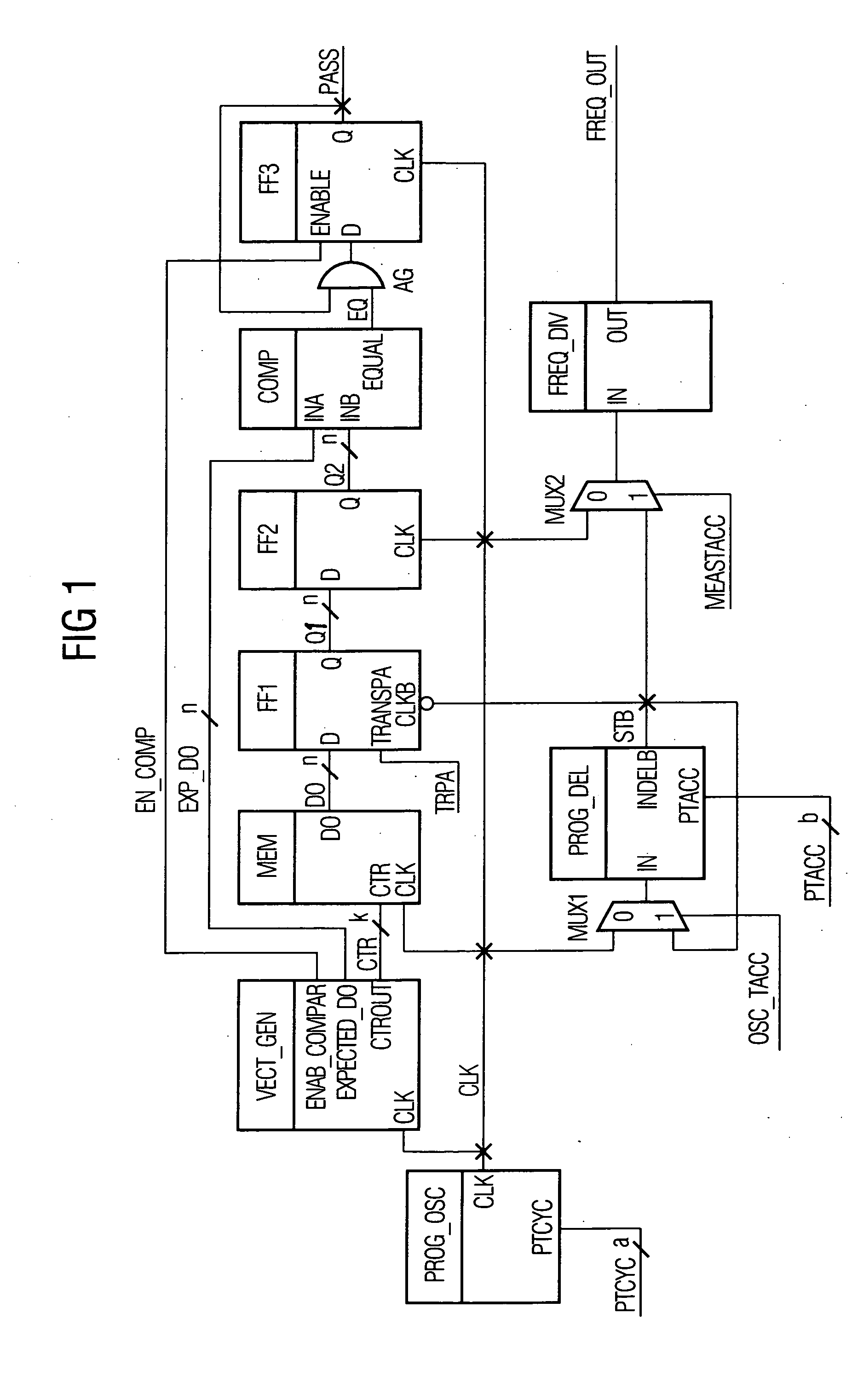
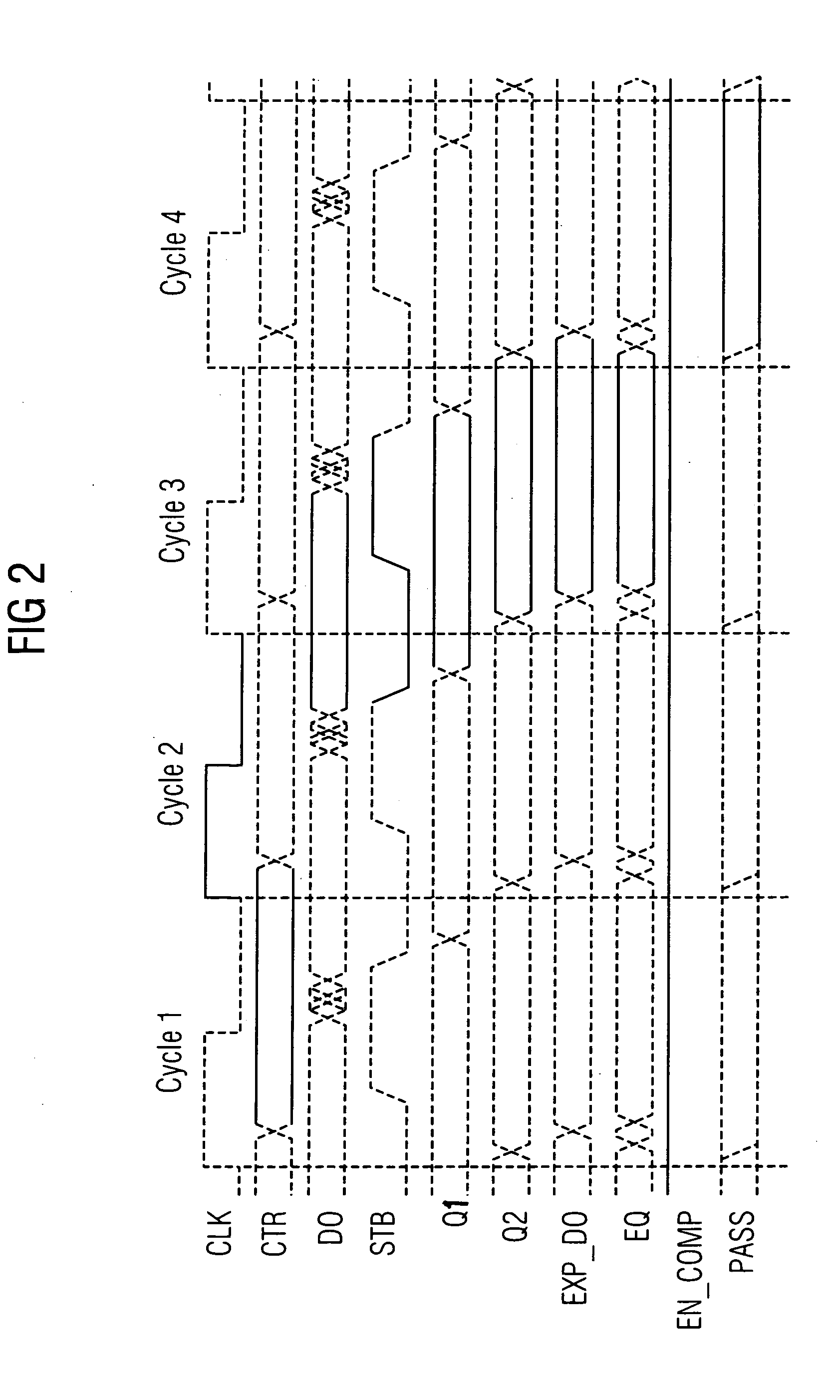
[0066]FIG. 1 shows the circuit diagram of an apparatus which is employed for determining the access time and / or the minimally allowable cycle time of a memory MEM. The memory MEM is an SRAM (Static Random Access Memory). The data outputs DO of the memory MEM are connected to the inputs D of a set of flip-flops FF1. The flip-flops FF1 and another set of flip-flops FF2 are connected in series.

[0067] The outputs Q of the flip-flops FF2 feed an input INB of a multi-bit comparator COMP. An input INA of the multi-bit comparator COMP is fed by a vector generator VECT_GEN. The vector generator VECT_GEN also feeds the control inputs CTR of the memory MEM.

[0068] The multi-bit comparator COMP performs the comparison of two words each composed of one or more bits. One of these words feeds the input INA and the other word feeds the input INB of the multi-bit comparator COMP. The multi-bit comparator COMP outputs at its output EQUAL a single bit which shows a high logical level if the two words...


PUM


Abstract

An apparatus for determining the access time and the minimally allowable cycle time of a memory, comprising a clock for generating a signal which stimulates memory data output, programmable delay means for generating a delayed signal, sample-and-hold means for sampling the data output of the memory in response to the delayed signal, a comparator for comparing the sampled data to reference values, and a test status generator, wherein the test status depends on the results of more than one of the comparisons.

Description

CROSS-REFERENCE TO RELATED APPLICATIONS [0001] This application claims foreign priority benefits under 35 U.S.C. §119 to co-pending European patent application number EP 04 290 106.6, filed 15 Jan. 2004. This related patent application is herein incorporated by reference in its entirety. BACKGROUND OF THE INVENTION [0002] 1. Field of the Invention [0003] The invention broadly relates to built in test modules for integrated circuits and deals more particularly with an apparatus for determining the access time and / or the minimally allowable cycle time of a memory forming part of an integrated circuit chip. In particular the invention also relates to test chips and especially to library test chips. [0004] 2. Description of the Related Art [0005] To confirm the functionality of chips before they are shipped, electronic testers are employed to test the functionality of each chip. One of the goals is to measure or to determine timings which characterize the performance of the device under...

Claims


Application Information

Patent Timeline
IPC IPC(8): G01R31/28G06F11/00G11C29/00
CPCG11C29/50012
Inventor GOUIN, VINCENTBORRI, SIMONETELLIER, YANN
Owner INFINEON TECH AG INFINEON
Why Eureka
Try Eureka